
You are looking for information, articles, knowledge about the topic nail salons open on sunday near me multimeter showing -1 on Google, you do not find the information you need! Here are the best content compiled and compiled by the Chewathai27.com team, along with other related topics such as: multimeter showing -1 multimeter won t turn on, multimeter continuity, multimeter fault finding, multimeter won t zero, multimeter circuit, multimeter repair, how to use a multimeter, multimeter only reads ol
Contents
How do you reset a multimeter?
- Set the multimeter to the highest resistance range by turning the dial to the highest “ohm” setting.
- Touch the test probes of your digital multimeter together. …
- Press the calibration knob until the display reads “0” on the digital multimeter if you don’t see “0 ohms” initially.
Why does multimeter show negative?
If they are switched, there will be a negative voltage. If the poles of your voltmeter are correctly connected, there is a possibility that the battery suffered a phenomenon called “polarity reversal”. This is a rare phenomenon that can happen at the end of a discharge with 2 or more batteries in series.
Why does my multimeter read 1?
If the multimeter reads 1 or displays OL, it’s overloaded. You will need to try a higher mode such as 200kΩ mode or 2MΩ (megaohm) mode. There is no harm if this happen, it simply means the range knob needs to be adjusted. If the multimeter reads 0.00 or nearly zero, then you need to lower the mode to 2kΩ or 200Ω.
How do you tell if my multimeter is broken?
- If the multimeter doesn’t turn on or the display is dim you may have a weak or dead battery. …
- If your multimeter powers up but you aren’t getting accurate measurements you may have faulty test leads.
What does it mean to have negative voltage?
A negative voltage is a relative excess of electrons compared to some other point. If 0 V is no voltage. Negative voltage is an excess of electrons and positive voltage is a deficiency of electrons.
What causes negative resistance?
Differential negative resistance happens when the electrical energy is in the form of alternating current. Both dynamic and static resistance are measured in ohms, and of course, they conform to Ohm’s law. Unlike a simple resistor, a negative resistance component can amplify power, even if it has only two terminals.
Can you have a negative voltage?
The magnitude of a voltage can be either positive or negative.
What does the continuity symbol look like?
Generally, the continuity mode will have a diode symbol, which is a triangle with a line on the right side. It may also have a symbol that looks like soundwaves.
What is the symbol for continuity?
Continuity: Usually denoted by a wave or diode symbol. This simply tests whether or not a circuit is complete by sending a very small amount of current through the circuit and seeing if it makes it out the other end. If not, then there’s something along the circuit that’s causing a problem—find it!
What are the symbols on a fluke meter?
…
Digital multimeter jacks
- A (amps) …
- mA, μA (milliamps, microamps) …
- COM. …
- Voltage (V), resistance (Ω), diode test (arrow plus symbol), capacitance (other symbol), temperature.
What does 0 mean on a multimeter?
On a digital multimeter, infinity reads “0. L.” On a VOM, “zero” means a closed circuit has been detected. The display needle moves to the far right side of an analog scale; “zero” reads “0.00” on a digital VOM.
What does a reading of 0 ohms mean?
Resistance, symbolized by the (Ω) symbol and measured in Ohms, is a measurement of how well a current can travel through a circuit or a given path. A circuit with no resistance (0) would indicate a complete circuit, or one that has no short.
Why does my multimeter not read 0?
If it’s a true-RMS meter, it’s perfectly normal that it doesn’t read zero in AC mode with the leads shorted. The response of the True-RMS converter is not exactly linear close to 0V, so they adjust it so it’s accurate in the linear part. The accuracy specs are usually not valid below 20% of full-scale or so.
Why is my multimeter not reading current?
If you try to measure the current with a blown fuse, you’ll probably notice that the meter reads ‘0.00’ and that the system doesn’t turn on like it should when you attach the multimeter. This is because the internal fuse is broken and acts as a broken wire or open.
How do I know if my multimeter is calibrated?
Turn the dial or setting selector on the face of the multimeter to the lowest Ohm setting. This usually is around 100 Ohms. Touch the black ground point to the red lead point and examine the readout of the multimeter. A perfectly calibrated multimeter will read exactly 0 Ohms.
Do you need to calibrate a multimeter?
Multimeters need to be calibrated from time to time to ensure continued accuracy. Calibration confirms that the multimeter’s performance meets the required specifications.
Step-by-Step: How To Troubleshoot with a Multimeter – Central Turf and Irrigation Supply
- Article author: www.centraltis.com
- Reviews from users: 39358
 Ratings
 - Top rated: 3.3
- Lowest rated: 1
- Summary of article content: Articles about Step-by-Step: How To Troubleshoot with a Multimeter – Central Turf and Irrigation Supply Touch the second meter lead to each of the station terminals, and record the resistance readings. Compare your readings to the acceptable range of 20 – 60 ohms. …
- Most searched keywords: Whether you are looking for Step-by-Step: How To Troubleshoot with a Multimeter – Central Turf and Irrigation Supply Touch the second meter lead to each of the station terminals, and record the resistance readings. Compare your readings to the acceptable range of 20 – 60 ohms.
- Table of Contents:
How to Calibrate a Digital Multimeter | Hunker
- Article author: www.hunker.com
- Reviews from users: 40217 Ratings
- Top rated: 3.3
- Lowest rated: 1
- Summary of article content: Articles about How to Calibrate a Digital Multimeter | Hunker Updating …
- Most searched keywords: Whether you are looking for How to Calibrate a Digital Multimeter | Hunker Updating A digital multimeter is used to measure voltage, current and resistance and can be used to measure electrical continuity in a circuit. The digital display on the multimeter shows the numerical measured value of voltage, current or resistance.
- Table of Contents:
Step 1
Step 2
Step 3
Why does the battery show a minus voltage when checked with the voltmeter? | Panasonic Batteries
- Article author: www.panasonic-batteries.com
- Reviews from users: 39477 Ratings
- Top rated: 3.7
- Lowest rated: 1
- Summary of article content: Articles about Why does the battery show a minus voltage when checked with the voltmeter? | Panasonic Batteries Updating …
- Most searched keywords: Whether you are looking for Why does the battery show a minus voltage when checked with the voltmeter? | Panasonic Batteries Updating Make sure you measure the correct way: connect the poles to their corresponding measuring ends.
- Table of Contents:
What Do The Symbols On A Multimeter Mean-Easy Tutorial – YouTube
- Article author: www.youtube.com
- Reviews from users: 15196 Ratings
- Top rated: 4.1
- Lowest rated: 1
- Summary of article content: Articles about What Do The Symbols On A Multimeter Mean-Easy Tutorial – YouTube Updating …
- Most searched keywords: Whether you are looking for What Do The Symbols On A Multimeter Mean-Easy Tutorial – YouTube Updating In this video, I talk to you about the symbols on a multimeter. I tell you what they mean and explain exactly how to decipher between the many symbols that y…what do the symbols on a multimeter mean, symbols on a multimeter, multimeter symbols, multimeter symbols meaning, meaning of multimeter symbols, using a multimeter, multimeter tutorial, multimeter symbol tutorial
- Table of Contents:

How to Use a Multimeter – learn.sparkfun.com
- Article author: learn.sparkfun.com
- Reviews from users: 12544 Ratings
- Top rated: 4.5
- Lowest rated: 1
- Summary of article content: Articles about How to Use a Multimeter – learn.sparkfun.com Updating …
- Most searched keywords: Whether you are looking for How to Use a Multimeter – learn.sparkfun.com Updating
- Table of Contents:
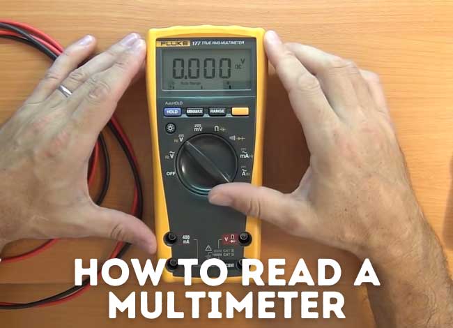
How to Read a Multimeter
- Article author: bestmultimeterreviews.org
- Reviews from users: 16403 Ratings
- Top rated: 4.1
- Lowest rated: 1
- Summary of article content: Articles about How to Read a Multimeter Updating …
- Most searched keywords: Whether you are looking for How to Read a Multimeter Updating
- Table of Contents:
How to read the dial settings
Reading an analog multimeter result
MultiMeter Level and Loudness controls in Final Cut Pro – Apple Support (VN)
- Article author: support.apple.com
- Reviews from users: 44144 Ratings
- Top rated: 3.2
- Lowest rated: 1
- Summary of article content: Articles about MultiMeter Level and Loudness controls in Final Cut Pro – Apple Support (VN) The MultiMeter effect’s Level meter displays the current signal level on a logarithmic scale. The Loudness meter shows the perceived level of a signal. …
- Most searched keywords: Whether you are looking for MultiMeter Level and Loudness controls in Final Cut Pro – Apple Support (VN) The MultiMeter effect’s Level meter displays the current signal level on a logarithmic scale. The Loudness meter shows the perceived level of a signal. In Final Cut Pro, the MultiMeter effect’s Level meter displays the current signal level on a logarithmic decibel scale. The Loudness meter shows the perceived level of a signal.
- Table of Contents:
Final Cut Pro Logic Effects
Level meter controls
Apple Footer
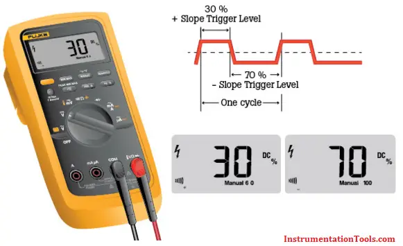
How to Measure Duty Cycle using Multimeter – Inst Tools
- Article author: instrumentationtools.com
- Reviews from users: 11587 Ratings
- Top rated: 3.7
- Lowest rated: 1
- Summary of article content: Articles about How to Measure Duty Cycle using Multimeter – Inst Tools Updating …
- Most searched keywords: Whether you are looking for How to Measure Duty Cycle using Multimeter – Inst Tools Updating
- Table of Contents:
Categories
Recent Comments
Buy CEM DT-3260 Digital Multimeter Display Counts 6000 Online At Best Price On Moglix
- Article author: www.moglix.com
- Reviews from users: 46302 Ratings
- Top rated: 4.1
- Lowest rated: 1
- Summary of article content: Articles about Buy CEM DT-3260 Digital Multimeter Display Counts 6000 Online At Best Price On Moglix Updating …
- Most searched keywords: Whether you are looking for Buy CEM DT-3260 Digital Multimeter Display Counts 6000 Online At Best Price On Moglix Updating Buy CEM DT-3260 Digital Multimeter Display Counts 6000 Online in India at moglix. Shop from the huge range of CEM Multimeters. ✯ Branded Multimeters ✯ Lowest Price ✯ Best Deals ✯ CODCEM DT-3260 Digital Multimeter Display Counts 6000, Multimeters, CEM
- Table of Contents:
AEMC Digital Multimeters | Portable True RMS Multimeter
- Article author: www.weschler.com
- Reviews from users: 45376 Ratings
- Top rated: 4.1
- Lowest rated: 1
- Summary of article content: Articles about AEMC Digital Multimeters | Portable True RMS Multimeter Updating …
- Most searched keywords: Whether you are looking for AEMC Digital Multimeters | Portable True RMS Multimeter Updating The AEMC MTX series portable hand-held True RMS multimeters with digital display (Models MTX 3290 & MTX 3291) and graphical color display.
- Table of Contents:
Description
Related products

See more articles in the same category here: Chewathai27.com/toplist.
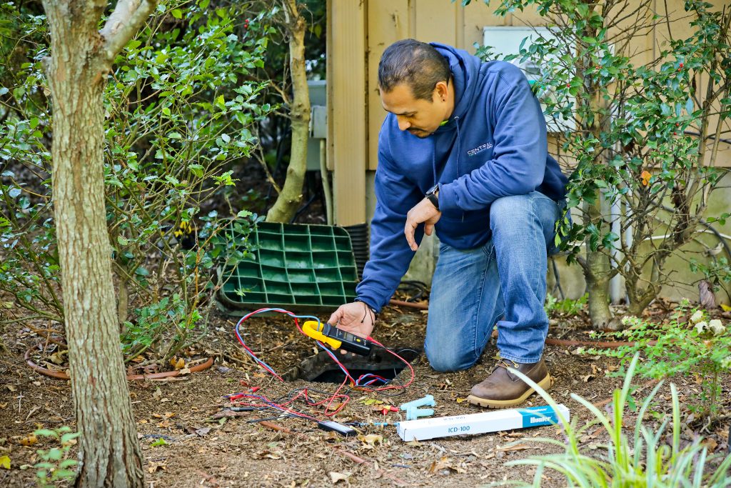
Step-by-Step: How To Troubleshoot with a Multimeter
Winter is coming to an end and spring will be here in no time. Now is the time to prepare for the irrigation start-up season! As with every season, there may be some tasks you need to check off your list before fully being 100% ready to go. As your business returns to work, you may come across a few systems that are not functioning or working properly. Troubleshooting can be frustrating and can take up valuable time from your projects in the future. If the system is through a manufacturer you are unfamiliar with, sourcing the resources you need quickly can feel impossible.
That’s why we’ve connected with Doug Armour, Central’s Commercial Irrigation Technical Manager, to share his insight on what to do when an irrigation system is not working properly. Armour is certified by the Irrigation Association as a Landscape Irrigation Water Manager, in addition he holds certifications with Hunter & Rain Bird, and has been factory trained with Tucor. He is an excellent resource for any technical questions about irrigation systems and for troubleshooting systems that are not functioning properly.
From Doug:
Central’s marketing department asked me to write a piece on troubleshooting irrigation systems. As soon as it was time to put pen to paper, the calls started coming from the field to troubleshoot systems in real life. Since our seasonal sprint is starting, I want to keep this piece very direct and as simple as possible.
When a watering zone will not activate, the best tool you can use for troubleshooting is a multimeter. It is a critical piece of equipment that every irrigation contractor truck should have. A multimeter is an inexpensive piece of equipment and its capable of troubleshooting a variety of problems with an irrigation system, including AC and DC voltage, and resistance. It can help identify issues with solenoids, valves, field wiring, and controllers.
This piece of equipment is really worth the investment and will pay for itself time and again. Get one. Armada has several multimeters to choose from, you’ll be able to find one that makes sense for your business. If you also install landscape lighting, consider getting a true RMS multimeter because you will be able to use it for both irrigation and landscape lighting.
5 Terms to Know When Troubleshooting a System:
AC volts (VAC) – Alternating Current, this is household voltage. Most irrigation solenoids operate on AC voltage. DC volts (VDC) – Direct Current, the normal source is a battery. DC voltage is polarized, meaning that there is a positive(+) and a negative(-), sometimes referred to as ground. Note: The meter must be connected properly to prevent meter damage, the RED lead is(+), and the BLACK lead is(-). Resistance (ohms Cl) – A measurement of how difficult it is for the current to flow through the electrical system. This is very similar to friction loss through a piece of PVC pipe.
Resistance is the most useful function for troubleshooting irrigation systems. For irrigation applications, a solenoid is considered to be good if its resistance is between 20 -60 ohms. Two terms to understand under resistance are as follows:
Short – when the resistance measured is below 20 ohms for a single solenoid. This allows excess current to flow through the circuit breaker or fuse. If the amount of current exceeds the rating of the devise, it will open, therefore stopping the 24 volts to the valves. Open – when the resistance is above 60 ohms, the flow of current to the solenoid is reduced. Think of this as having a rock lodged in the mainline of a sprinkler system. The resistance may increase to the point that the solenoid does not get enough voltage to operate.
Using the Multimeter
Make sure to take the time to read the instructions on your multimeter. Knowing how to operate a meter will save considerable time when testing the wiring on a job site.
4 Basic steps for using the meter:
Disconnect the common wire(s) from the terminal strip on the controller. Turn the dial to the resistance or Ohms setting (this looks different on every meter) Connect one of the meter leads to the common wire, not the controller common terminal. Touch the second meter lead to each of the station terminals, and record the resistance readings.
Compare your readings to the acceptable range of 20 – 60 ohms. The reading will give you insight into the problem. See the possible outcomes and recommended action below:
Acceptable Range:
If the measurements are within the acceptable range (20 – 60 ohms) then the electrical circuit for that station is good. Just note, that this test only inspects the condition of the wiring, the station may not operate properly because of controller and/or valve problems.
A short:
If the resistance range is below 20 ohms (a short), proceed to the valve and disconnect the solenoid from the field wires. Test the resistance of the solenoid only. If the measurement is still low, then the solenoid must be replaced. If the solenoid resistance is acceptable, then the short is in the field wiring itself (two solenoids connected to the station can also produce a low reading). Wire tracing equipment should be used to locate the problem.
An open:
If the resistance is above 60 ohms (an open), test the solenoid without the field wires connected. Replace the solenoid if its resistance is still above 60 ohms. More than likely, the solenoid will test within proper limits of between 20 – 60 ohms.
If the solenoid is good:
Cut out the wire connectors and connect the station and common wires together at the valve location. From the controller, re-test the resistance without the solenoid in the circuit. The resistance should now read very low, possibly 5 ohms or below since only the resistance of the field wires is being measured. If the resistance is this low, then the problem was a faulty wire connector. Install new waterproof wire connectors on the existing solenoid and test the resistance again at the controller.
What if the resistance is still high?
If the resistance is still high when the common and station wires are connected together, then there is an open somewhere between the valve and the controller, possibly caused by a faulty wire or wire connector. Unfortunately, this fault can only be found with the use of wire tracing equipment.
This final field wiring test will determine shorts directly into the earth:
In addition to the common still being disconnected, remove each of the station wires from the controller. Connect one of the meter leads to a piece of bare wire wrapped around the metal shaft of a screwdriver. Insert the screwdriver into the ground (it may be necessary to wet the ground to assure a good connection). Touch the second lead to the station wires and the common one at a time. Each of these measurements should be above 700K (700,000) ohms.
A resistance reading of below 700,000 would indicate a section of the wire has a nick in the insulation and is making contact with the earth. Wire tracing equipment should be used to locate the problem.
Transformers can also be tested using a multimeter.
Connect the meter leads to the primary winding, that Is, the transformer input wires or plug in connectors. You will either get a resistance reading or an open. A resistance reading shows the internal windings are intact, an open indicates the transformer’s internal fuse is bad and the transformer must be replaced.
The secondary winding, the transformer output, is tested the same way. Connect the meter leads to the output wires. An open indicates that the transformer must be replaced. The 20 – 60 ohm rule does not apply to transformers. It Is common to find resistance as low as 3 ohms.
A multimeter may also be used to determine what type of battery should be used in a solid-state controller.
The controller should be powered up and the battery removed from its connector. Rotate the dial to the DC V setting. There are two battery connectors, a large one (female) and a smaller one (male). Touch the red probe to the large connector, the black probe to the small connector. If the controller is designed to accept an alkaline battery, the reading will be close to zero volts. If it is designed to accept a rechargeable NiCad battery, the reading will be between 7 and 13 volts DC.
Just a reminder: never use an alkaline battery in a controller designed to accept a rechargeable battery. Also, do not use rechargeable alkaline batteries in solid-state controllers.
As mentioned earlier, troubleshooting can be very frustrating and not always straight forward. A system might have more than one issue. Rely on Central to help, whether it’s questions about troubleshooting or installation, showing you how to use specific equipment, or sharing insight and recommendations on the newest technologies. We stay at the leading edge of the industry and we’re ready to help you grow!
About Doug Armour
Doug Armour is certified by the Irrigation Association as a Landscape Irrigation Water Manager, in addition he holds certifications with Hunter and Rain Bird, and has been factory trained with Tucor. He is an excellent resource for any technical questions about irrigation systems and for troubleshooting systems that are not working properly.
How to Use a Multimeter
Favorited Favorite 63
Measuring Resistance
Normal resistors have color codes on them. If you don’t know what they mean, that’s ok! There are plenty of online calculators that are easy to use. However, if you ever find yourself without internet access, a multimeter is very handy at measuring resistance.
Pick out a random resistor and set the multimeter to the 20kΩ setting. Then hold the probes against the resistor legs with the same amount of pressure you when pressing a key on a keyboard.
The meter will read one of three things, 0.00, 1, or the actual resistor value.
In this case, the meter reads 0.97, meaning this resistor has a value of 970Ω, or about 1kΩ (remember you are in the 20kΩ or 20,000 Ohm mode so you need to move the decimal three places to the right or 970 Ohms).
If the multimeter reads 1 or displays OL , it’s overloaded. You will need to try a higher mode such as 200kΩ mode or 2MΩ (megaohm) mode. There is no harm if this happen, it simply means the range knob needs to be adjusted.
If the multimeter reads 0.00 or nearly zero, then you need to lower the mode to 2kΩ or 200Ω.
Remember that many resistors have a 5% tolerance. This means that the color codes may indicate 10,000 Ohms (10kΩ), but because of discrepancies in the manufacturing process a 10kΩ resistor could be as low as 9.5kΩ or as high as 10.5kΩ. Don’t worry, it’ll work just fine as a pull-up or general resistor.
Let’s drop the meter down to the next lowest setting, 2KΩ. What happens?
Not a whole lot changed. Because this resistor (a 1KΩ) is less than 2KΩ, it still shows up on the display. However, you’ll notice that there is one more digit after the decimal point giving us a slightly higher resolution in our reading. What about the next lowest setting?
Now, since 1kΩ is greater than 200Ω, we’ve maxed out the meter, and it is telling you that it is overloaded and that you need to try a higher value setting.
As a rule of thumb, it’s rare to see a resistor less than 1 Ohm. Remember that measuring resistance is not perfect. Temperature can affect the reading a lot. Also, measuring resistance of a device while it is physically installed in a circuit can be very tricky. The surrounding components on a circuit board can greatly affect the reading.
How to Use a Multimeter
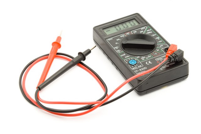
Need to check the life of a battery? Or do you need to diagnose a problem with wiring to an outlet in your home? A digital multimeter tester can help you solve these problems, which is why it’s a useful instrument to keep in your toolbox. A multimeter can be used to troubleshoot a wide variety of issues, and you can use this guide to learn how to use a multimeter in various DIY scenarios.
What Is a Multimeter and How Is It Used?
A multimeter, sometimes referred to as a volt-ohm meter, is a versatile tool for homeowners to keep on hand that tests different units of electricity—voltage (AC and DC), current, and resistance.
Voltage: Measured in volts, alternating current (AC) and direct current (DC), are two forms of voltage that a multimeter can test for. AC is the flow of an electrical current that changes directions, usually found in the electrical wiring throughout your home. DC is the flow of an electrical charge in one direction, normally used in batteries, vehicles, and other electronics.
Current: Current, which is measured in amps or amperage, tests the strength of a current to determine the amount of electricity that is flowing through a circuit. It’s an important safety measure to test the amount of current when you’re doing an electrical project, such as wiring a light switch, to ensure the electricity is completely off.
Resistance: Measuring resistance determines the opposite flow of electricity, using ohms as the unit of measurement. Resistors are most commonly used in household appliances and electrical devices.
Continuity: Continuity testing measures for a complete path of current. All circuits need a continuous path for electricity to flow through. For example, if an appliance fails, it could be because there’s an open circuit, meaning it’s devoid of continuity. Replacing the component could fix the appliance, allowing it to work properly again.
There are digital multimeters and analog multimeters that both perform the same function, but have a different display. A digital multimeter features an LCD display, whereas an analog multimeter has a needle that moves over a numerical scale.
Anatomy of a Multimeter
Photo: krisanapong detraphiphat / Getty Images
Learn about the different parts of a multimeter. Remember, the features can differ from model to model, so your multimeter may not have the exact same options as the ones listed.
Display: The display is the LCD screen (digital) or scale (analog) that depicts the reading of the electrical measurement.
Selection knob or button: This is the knob or button that allows you to switch between different units of measurement. Here are some of the abbreviations that you may see on your multimeter: AC volts (V with a wavy line over it) DC volts (V with three hyphens and a straight line on top) Resistance (ohms or Ω) Amps (A) Milliamps (mA) Continuity (diode symbol or a soundwave symbol)
Hold button: The hold button is used to keep track of a certain reading on the display, so you don’t need to write it down to recall the measurement at a later time.
Test probes: On a multimeter, there are two probes (also referred to as test leads) that are plugged into the ports with a male banana jack to test the electrical component. On the other end of the probe is a metal tip—sometimes referred to as the terminal. The red probe tests for a live current, and the black probe tests ground or neutral terminals.
Ports: Most multimeters have two or three ports to connect the leads to. All multimeters will have a common port, which is black, and labeled as COM for common. This is where the black probe will plug into. The mAVΩ port is the port that the red probe plugs into and used to test most electrical measurements, such as volts, resistance, and current. The mAVΩ port may also be labeled as VΩ or V. Your multimeter may also have a red 10A port, but it is used less often than the mAVΩ port and typically tests large currents (up to 10 amps).
Safety Precautions and Preparations
Now that you understand the basic uses and components of a multimeter, it’s important to take adequate safety measures when performing electrical work.
Inspect the multimeter for any signs of damage, such as cracks, dings, or leaks, to ensure a safe and accurate reading.
Wear insulated gloves and rubber shoes to add a layer of protection when performing electrical tests.
Don’t test any wires that are damaged or frayed.
Only perform electrical testing in dry conditions.
Never touch the metal tips of the probes with your hands.
Ensure the multimeter probes are working properly internally by “ohming-out” the leads. Put the multimeter in the resistance (ohms or Ω) setting, then connect the probes to the port (plug the black probe into the COM or common port and plug the red probe into the red mAVΩ port). Touch the tips of the probe together (making sure not to touch the tips with your hands), and check that the reading is 0.5 ohms or less. If the reading is over 0.5 ohms, you will need to replace the probes.
Always keep the multimeter in its case when not in use.
4 Ways to Use a Multimeter
Follow this guide to learn how to use a multimeter to measure AC or DC voltage, resistance, and continuity.
So you have finished reading the multimeter showing -1 topic article, if you find this article useful, please share it. Thank you very much. See more: multimeter won t turn on, multimeter continuity, multimeter fault finding, multimeter won t zero, multimeter circuit, multimeter repair, how to use a multimeter, multimeter only reads ol