
You are looking for information, articles, knowledge about the topic nail salons open on sunday near me find the current through each resistor for the circuit shown on Google, you do not find the information you need! Here are the best content compiled and compiled by the Chewathai27.com team, along with other related topics such as: find the current through each resistor for the circuit shown for the circuit shown in the figure(figure 1) find the current through each resistor, Determine the current through each resistor, Determine the current through each element in the circuit, Find the current flowing in the circuit in the following Figure, Current through resistor formula, Determine the voltage across the resistor, In a series circuit with 3 resistors, Resistance in series and parallel
Contents
How do you find the current through each resistor?
The potential drop across each resistor is the same. Current through each resistor can be found using Ohm’s law I=V/R, where the voltage is constant across each resistor.
How do you find the current in each resistor in a combination circuit?
The goal of the analysis is to determine the current in and the voltage drop across each resistor. Now the Ohm’s law equation (ΔV = I • R) can be used to determine the total current in the circuit. In doing so, the total resistance and the total voltage (or battery voltage) will have to be used.
What is the current flowing through the 2 ohm resistor?
In the circuit diagram, the current flowing through the 2 ohm resistor is 1 ampere.
What is current formula?
Current is usually denoted by the symbol I. Ohm’s law relates the current flowing through a conductor to the voltage V and resistance R; that is, V = IR. An alternative statement of Ohm’s law is I = V/R.
How do you find the current in a circuit?
- To find the Voltage, ( V ) V = I x R ] V (volts) = I (amps) x R (Ω)
- To find the Current, ( I ) [ I = V ÷ R ] I (amps) = V (volts) ÷ R (Ω)
- To find the Resistance, ( R ) [ R = V ÷ I ] R (Ω) = V (volts) ÷ I (amps)
- To find the Power (P) [ P = V x I ] P (watts) = V (volts) x I (amps)
Which combination of a 2 Ω resistor and 4 Ω resistor offers the least resistance to current in the circuit?
Parallel combination of 2ohm and 4ohm resistor offers the least resistance to current in the circuit.
What is R1 || R2?
For example, the notation R1||R2 indicates that the resistors R1 and R2 are in parallel. The notation R1||R2 is often used as shorthand notation for the equivalent resistance of the parallel resistance combination, in lieu of equation (5).
How do you find current in a parallel circuit?
Total current in a parallel circuit is the sum of the individual branch currents. This relationship in a parallel circuit is expressed as: IT = I1 + I2 + I3… Whenever more resistances are connected in parallel, they have the effect of reducing the overall circuit resistance.
How do you calculate resistance in a circuit?
If you know the total current and the voltage across the whole circuit, you can find the total resistance using Ohm’s Law: R = V / I. For example, a parallel circuit has a voltage of 9 volts and total current of 3 amps. The total resistance RT = 9 volts / 3 amps = 3 Ω.
What is the current through 20 ohm resistor?
V=20/3V So current through 20 ohm = V/20 = (20/3)/20 =1/3=0.33V.
What is the current in the 8 ohm resistor?
Current in 8Ω=I1+I2=0.
How do you find current with voltage and resistance?
From this, we conclude that; Current equals Voltage divided by Resistance (I=V/R), Resistance equals Voltage divided by Current (R=V/I), and Voltage equals Current times Resistance (V=IR).
Attention Required! | Cloudflare
- Article author: www.toppr.com
- Reviews from users: 41778
 Ratings
 - Top rated: 3.0
- Lowest rated: 1
- Summary of article content: Articles about Attention Required! | Cloudflare In the circuit given below, find the total current drawn from the battery: · If in the circuit power dissipation is 150 W, then R is. …
- Most searched keywords: Whether you are looking for Attention Required! | Cloudflare In the circuit given below, find the total current drawn from the battery: · If in the circuit power dissipation is 150 W, then R is.
- Table of Contents:
Please complete the security check to access wwwtopprcom
Why do I have to complete a CAPTCHA
What can I do to prevent this in the future
10.3: Resistors in Series and Parallel – Physics LibreTexts
- Article author: phys.libretexts.org
- Reviews from users: 40030 Ratings
- Top rated: 4.1
- Lowest rated: 1
- Summary of article content: Articles about 10.3: Resistors in Series and Parallel – Physics LibreTexts Updating …
- Most searched keywords: Whether you are looking for 10.3: Resistors in Series and Parallel – Physics LibreTexts Updating Basically, a resistor limits the flow of charge in a circuit and is an ohmic device where V=IR. Most circuits have more than one resistor. If several resistors are connected together and connected …
- Table of Contents:
Resistors in Series
Resistors in Parallel
Combinations of Series and Parallel
Practical Implications

Physics Tutorial: Combination Circuits
- Article author: www.physicsclassroom.com
- Reviews from users: 25472 Ratings
- Top rated: 5.0
- Lowest rated: 1
- Summary of article content: Articles about
Physics Tutorial: Combination Circuits
Updating … - Most searched keywords: Whether you are looking for
Physics Tutorial: Combination Circuits
Updating When all the devices in a circuit are connected by series connections, then the circuit is referred to as a series circuit. When all the devices in a circuit are connected by parallel connections, then the circuit is referred to as a parallel circuit. A third type of circuit involves the dual use of series and parallel connections in a circuit; such circuits are referred to as compound circuits or combination circuits. This lesson focuses on how to analyze a combination circuit.circuits, electricity, current, electric circuits, circuit symbols, schematic diagrams, series circuits, parallel circuits, combination circuits, Kirchoffs Laws, equivalent resistance, voltage drops, Ohm’s law, branch current, compound circuits - Table of Contents:
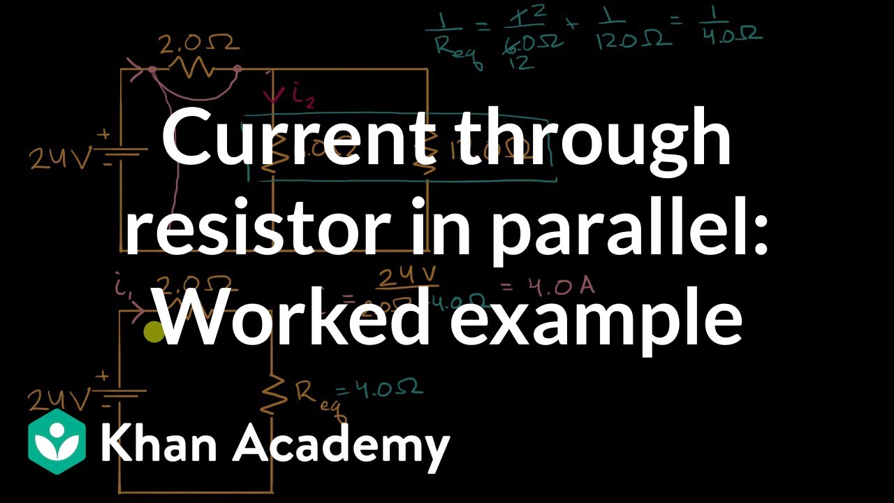
Current through resistor in parallel: Worked example | DC Circuits | AP Physics 1 | Khan Academy – YouTube
- Article author: www.youtube.com
- Reviews from users: 39953 Ratings
- Top rated: 4.6
- Lowest rated: 1
- Summary of article content: Articles about Current through resistor in parallel: Worked example | DC Circuits | AP Physics 1 | Khan Academy – YouTube Updating …
- Most searched keywords: Whether you are looking for Current through resistor in parallel: Worked example | DC Circuits | AP Physics 1 | Khan Academy – YouTube Updating How to calculate the current through a resistor in parallel using equivalent resistance and Ohm’s law.View more lessons or practice this subject at https://w…online learning, online class, video class, video tutorial, online education
- Table of Contents:
Finding The Current In a Parallel Circuit With 3 Resistors – YouTube
- Article author: www.youtube.com
- Reviews from users: 42498 Ratings
- Top rated: 3.1
- Lowest rated: 1
- Summary of article content: Articles about Finding The Current In a Parallel Circuit With 3 Resistors – YouTube Updating …
- Most searched keywords: Whether you are looking for Finding The Current In a Parallel Circuit With 3 Resistors – YouTube Updating This electronics video tutorial explains how to find the current in a parallel circuit with 3 resistors using a special formula. It also explains how to fin…parallel circuit, ohm’s law, electronics, resistors, current
- Table of Contents:

Access to this page has been denied.
- Article author: www.chegg.com
- Reviews from users: 12854 Ratings
- Top rated: 4.5
- Lowest rated: 1
- Summary of article content: Articles about Access to this page has been denied. Question: Find the current through each resistor for the circuit shown. This problem has been solved! See the answer … …
- Most searched keywords: Whether you are looking for Access to this page has been denied. Question: Find the current through each resistor for the circuit shown. This problem has been solved! See the answer …
- Table of Contents:
Find the current in each resistor in the circuit as shown in fig.
- Article author: www.doubtnut.com
- Reviews from users: 23686 Ratings
- Top rated: 3.8
- Lowest rated: 1
- Summary of article content: Articles about Find the current in each resistor in the circuit as shown in fig. The circuit can be redrawn as follows: Loop afdca: (2 +3)I1 +4(I1 +I2 ) = 10+25 or 9I(1) +4I(2) = 35 (i) Loop edcbe: (1 +9)I(2) +4(I(1) … …
- Most searched keywords: Whether you are looking for Find the current in each resistor in the circuit as shown in fig. The circuit can be redrawn as follows: Loop afdca: (2 +3)I1 +4(I1 +I2 ) = 10+25 or 9I(1) +4I(2) = 35 (i) Loop edcbe: (1 +9)I(2) +4(I(1) … The circuit can be redrawn as follows: Loop afdca: (2 +3)I1 +4(I1 +I2 ) = 10+25 or 9I(1) +4I(2) = 35 (i) Loop edcbe: (1 +9)I(2) +4(I(1) +I(2)) = 15 +25 or 4I(1) +14I(2) = 40 (ii) From Eqs (i) and (ii) we get I(1) = 3A, I(2) = 2A.
- Table of Contents:

For the circuit shown in the figure(figure 1) find the current through each resistor
- Article author: www.buzzsprout.com
- Reviews from users: 32170 Ratings
- Top rated: 4.6
- Lowest rated: 1
- Summary of article content: Articles about For the circuit shown in the figure(figure 1) find the current through each resistor Questions: Find the current through each resistor for the circuit in Figure 1.(A). Find the current through each res… …
- Most searched keywords: Whether you are looking for For the circuit shown in the figure(figure 1) find the current through each resistor Questions: Find the current through each resistor for the circuit in Figure 1.(A). Find the current through each res… This podcast will provide additional information about: “For the circuit shown in the figure(figure 1) find the current through each resistor”. We must not forget about the content!Questions: Find the current through each resistor for the circuit in Figure 1.(A). Find the current through each res…
- Table of Contents:

10.3: Resistors in Series and Parallel – Physics LibreTexts
- Article author: phys.libretexts.org
- Reviews from users: 17426 Ratings
- Top rated: 3.9
- Lowest rated: 1
- Summary of article content: Articles about 10.3: Resistors in Series and Parallel – Physics LibreTexts Updating …
- Most searched keywords: Whether you are looking for 10.3: Resistors in Series and Parallel – Physics LibreTexts Updating Basically, a resistor limits the flow of charge in a circuit and is an ohmic device where V=IR. Most circuits have more than one resistor. If several resistors are connected together and connected …
- Table of Contents:
Resistors in Series
Resistors in Parallel
Combinations of Series and Parallel
Practical Implications
See more articles in the same category here: https://chewathai27.com/toplist.
10.3: Resistors in Series and Parallel
Learning Objectives By the end of the section, you will be able to: Define the term equivalent resistance
Calculate the equivalent resistance of resistors connected in series
Calculate the equivalent resistance of resistors connected in parallel
In Current and Resistance, we described the term ‘resistance’ and explained the basic design of a resistor. Basically, a resistor limits the flow of charge in a circuit and is an ohmic device where \(V = IR\). Most circuits have more than one resistor. If several resistors are connected together and connected to a battery, the current supplied by the battery depends on the equivalent resistance of the circuit.
The equivalent resistance of a combination of resistors depends on both their individual values and how they are connected. The simplest combinations of resistors are series and parallel connections (Figure \(\PageIndex{1}\)). In a series circuit, the output current of the first resistor flows into the input of the second resistor; therefore, the current is the same in each resistor. In a parallel circuit, all of the resistor leads on one side of the resistors are connected together and all the leads on the other side are connected together. In the case of a parallel configuration, each resistor has the same potential drop across it, and the currents through each resistor may be different, depending on the resistor. The sum of the individual currents equals the current that flows into the parallel connections.
Figure \(\PageIndex{1}\): (a) For a series connection of resistors, the current is the same in each resistor. (b) For a parallel connection of resistors, the voltage is the same across each resistor.
Resistors in Series Resistors are said to be in series whenever the current flows through the resistors sequentially. Consider Figure \(\PageIndex{2}\), which shows three resistors in series with an applied voltage equal to \(V_{ab}\). Since there is only one path for the charges to flow through, the current is the same through each resistor. The equivalent resistance of a set of resistors in a series connection is equal to the algebraic sum of the individual resistances. Figure \(\PageIndex{2}\): (a) Three resistors connected in series to a voltage source. (b) The original circuit is reduced to an equivalent resistance and a voltage source. In Figure \(\PageIndex{2}\), the current coming from the voltage source flows through each resistor, so the current through each resistor is the same. The current through the circuit depends on the voltage supplied by the voltage source and the resistance of the resistors. For each resistor, a potential drop occurs that is equal to the loss of electric potential energy as a current travels through each resistor. According to Ohm’s law, the potential drop \(V\) across a resistor when a current flows through it is calculated using the equation \(V = IR\), where \(I\) is the current in amps (\(A\)) and \(R\) is the resistance in ohms \((\Omega)\). Since energy is conserved, and the voltage is equal to the potential energy per charge, the sum of the voltage applied to the circuit by the source and the potential drops across the individual resistors around a loop should be equal to zero: \[\sum_{i = 1}^N V_i = 0.\] This equation is often referred to as Kirchhoff’s loop law, which we will look at in more detail later in this chapter. For Figure \(\PageIndex{2}\), the sum of the potential drop of each resistor and the voltage supplied by the voltage source should equal zero: \[\begin{align*} V – V_1 – V_2 – V_3 &= 0, \\[4pt] V &= V_1 + V_2 + V_3, \\[4pt] &= IR_1 + IR_2 + IR_3, \end{align*}\] Solving for \(I\) \[\begin{align*} I &= \frac{V}{R_1 + R_2 + R_3} \\[4pt] &= \frac{V}{R_{S}}. \end{align*}\] Since the current through each component is the same, the equality can be simplified to an equivalent resistance (\(R_{S}\)), which is just the sum of the resistances of the individual resistors. Equivalent Resistance in Series Circuits Any number of resistors can be connected in series. If \(N\) resistors are connected in series, the equivalent resistance is \[R_{S} = R_1 + R_2 + R_3 + . . . + R_{N-1} + R_N = \sum_{i=1}^N R_i. \label{equivalent resistance series}\] One result of components connected in a series circuit is that if something happens to one component, it affects all the other components. For example, if several lamps are connected in series and one bulb burns out, all the other lamps go dark. Example \(\PageIndex{1}\): Equivalent Resistance, Current, and Power in a Series Circuit A battery with a terminal voltage of 9 V is connected to a circuit consisting of four \(20 \, \Omega\) and one \(10 \, \Omega\) resistors all in series (Figure \(\PageIndex{3}\)). Assume the battery has negligible internal resistance. Calculate the equivalent resistance of the circuit. Calculate the current through each resistor. Calculate the potential drop across each resistor. Determine the total power dissipated by the resistors and the power supplied by the battery. Figure \(\PageIndex{3}\): A simple series circuit with five resistors. Strategy In a series circuit, the equivalent resistance is the algebraic sum of the resistances. The current through the circuit can be found from Ohm’s law and is equal to the voltage divided by the equivalent resistance. The potential drop across each resistor can be found using Ohm’s law. The power dissipated by each resistor can be found using \(P = I^2R\), and the total power dissipated by the resistors is equal to the sum of the power dissipated by each resistor. The power supplied by the battery can be found using \(P = I\epsilon\). Solution The equivalent resistance is the algebraic sum of the resistances (Equation \ref{equivalent resistance series}): \[\begin{align*} R_{S} &= R_1 + R_2 + R_3 + R_4 + R_5 \\[4pt] &= 20 \, \Omega + 20 \, \Omega + 20 \, \Omega + 20 \, \Omega + 10 \, \Omega = 90 \, \Omega. \end{align*}\] The current through the circuit is the same for each resistor in a series circuit and is equal to the applied voltage divided by the equivalent resistance: \[I = \frac{V}{R_{S}} = \frac{9 \, V}{90 \, \Omega} = 0.1 \, A.
onumber\] Note that the sum of the potential drops across each resistor is equal to the voltage supplied by the battery. The power dissipated by a resistor is equal to \(P = I^2R\), and the power supplied by the battery is equal to \(P = I\epsilon\). \[P_1 = P_2 = P_3 = P_4 = (0.1 \, A)^2 (20 \, \Omega) = 0.2 \, W,
onumber\] \[P_5 = (0.1 \, A)^2 (10 \, \Omega) = 0.1 \, W,
onumber\] \[P_{dissipated} = 0.2 \, W + 0.2 \, W + 0.2 \, W + 0.2 \, W + 0.1 \, W = 0.9 \, W,
onumber\] \[P_{source} = I\epsilon = (0.1 \, A)(9 \, V) = 0.9 \, W.
onumber\] Significance There are several reasons why we would use multiple resistors instead of just one resistor with a resistance equal to the equivalent resistance of the circuit. Perhaps a resistor of the required size is not available, or we need to dissipate the heat generated, or we want to minimize the cost of resistors. Each resistor may cost a few cents to a few dollars, but when multiplied by thousands of units, the cost saving may be appreciable. Exercise \(\PageIndex{1}\) Some strings of miniature holiday lights are made to short out when a bulb burns out. The device that causes the short is called a shunt, which allows current to flow around the open circuit. A “short” is like putting a piece of wire across the component. The bulbs are usually grouped in series of nine bulbs. If too many bulbs burn out, the shunts eventually open. What causes this? Answer The equivalent resistance of nine bulbs connected in series is 9R. The current is \(I = V/9 \, R\). If one bulb burns out, the equivalent resistance is 8R, and the voltage does not change, but the current increases \((I = V/8 \, R\). As more bulbs burn out, the current becomes even higher. Eventually, the current becomes too high, burning out the shunt. Let’s briefly summarize the major features of resistors in series: Series resistances add together to get the equivalent resistance (Equation \ref{equivalent resistance series}): \[R_{S} = R_1 + R_2 + R_3 + . . . + R_{N-1} + R_N = \sum_{i=1}^N R_i.\] The same current flows through each resistor in series. Individual resistors in series do not get the total source voltage, but divide it. The total potential drop across a series configuration of resistors is equal to the sum of the potential drops across each resistor.
Resistors in Parallel Figure \(\PageIndex{4}\) shows resistors in parallel, wired to a voltage source. Resistors are in parallel when one end of all the resistors are connected by a continuous wire of negligible resistance and the other end of all the resistors are also connected to one another through a continuous wire of negligible resistance. The potential drop across each resistor is the same. Current through each resistor can be found using Ohm’s law \(I = V/R\), where the voltage is constant across each resistor. For example, an automobile’s headlights, radio, and other systems are wired in parallel, so that each subsystem utilizes the full voltage of the source and can operate completely independently. The same is true of the wiring in your house or any building. Figure \(\PageIndex{4}\): Two resistors connected in parallel to a voltage source. (b) The original circuit is reduced to an equivalent resistance and a voltage source. The current flowing from the voltage source in Figure \(\PageIndex{4}\) depends on the voltage supplied by the voltage source and the equivalent resistance of the circuit. In this case, the current flows from the voltage source and enters a junction, or node, where the circuit splits flowing through resistors \(R_1\) and \(R_2\). As the charges flow from the battery, some go through resistor \(R_1\) and some flow through resistor \(R_2\). The sum of the currents flowing into a junction must be equal to the sum of the currents flowing out of the junction: \[\sum I_{in} = \sum I_{out}.
onumber\] This equation is referred to as Kirchhoff’s junction rule and will be discussed in detail in the next section. In Figure \(\PageIndex{4}\), the junction rule gives \(I = I_1 + I_2\). There are two loops in this circuit, which leads to the equations \(V = I_1R_1\) and \(I_1R_1 = I_2R_2\). Note the voltage across the resistors in parallel are the same ( \(V = V_1 = V_2\)) and the current is additive: \[ \begin{align*} I &= I_1 + I_2 \\[4pt] &= \frac{V_1}{R_1} + \frac{V_2}{R_2} \\[4pt] &= \frac{V}{R_1} + \frac{V}{R_2} \\[4pt] &= V \left( \frac{1}{R_1} + \frac{1}{R_2} \right) = \frac{V}{R_{P}}\end{align*}\] Solving for the \(R_{P}\) \[R_{P} = \left(\frac{1}{R_1} + \frac{1}{R_2} \right)^{-1}. \] Equivalent Resistance in Parallel Circuits Generalizing to any number of \(N\) resistors, the equivalent resistance \(R_{P}\) of a parallel connection is related to the individual resistances by \[R_{P} = \left( \frac{1}{R_1} + \frac{1}{R_2} + \frac{1}{R_3} + . . . + \frac{1}{R_{N-1}} + \frac{1}{R_N} \right)^{-1} = \left(\sum_{i=1}^N \frac{1}{R_i} \right)^{-1}. \label{10.3}\] This relationship results in an equivalent resistance \(R_{P}\) that is less than the smallest of the individual resistances. When resistors are connected in parallel, more current flows from the source than would flow for any of them individually, so the total resistance is lower. Example \(\PageIndex{2}\): Analysis of a parallel circuit Three resistors \(R_1 = 1.00 \, \Omega\), \(R_2 = 2.00 \, \Omega\), and \(R_3 = 2.00 \, \Omega\), are connected in parallel. The parallel connection is attached to a \(V = 3.00 \, V\) voltage source. What is the equivalent resistance? Find the current supplied by the source to the parallel circuit. Calculate the currents in each resistor and show that these add together to equal the current output of the source. Calculate the power dissipated by each resistor. Find the power output of the source and show that it equals the total power dissipated by the resistors. Strategy (a) The total resistance for a parallel combination of resistors is found using Equation \ref{10.3}. (Note that in these calculations, each intermediate answer is shown with an extra digit.) (b) The current supplied by the source can be found from Ohm’s law, substituting \(R_{P}\) for the total resistance \(I = \frac{V}{R_{P}}\). (c) The individual currents are easily calculated from Ohm’s law \(\left(I_i = \frac{V_i}{R_i}\right)\), since each resistor gets the full voltage. The total current is the sum of the individual currents: \[I = \sum_i I_i.
onumber\] (d) The power dissipated by each resistor can be found using any of the equations relating power to current, voltage, and resistance, since all three are known. Let us use \(P_i = V^2 /R_i\), since each resistor gets full voltage. (e) The total power can also be calculated in several ways, use \(P = IV\). Solution The total resistance for a parallel combination of resistors is found using Equation \ref{10.3}. Entering known values gives \[R_{P} = \left( \frac{1}{R_1} + \frac{1}{R_2} + \frac{1}{R_3} \right)^{-1} = \left(\frac{1}{1.00 \, \Omega} + \frac{1}{2.00 \, \Omega} + \frac{1}{2.00 \, \Omega} \right)^{-1} = 0.50 \, \Omega.
onumber\] The total resistance with the correct number of significant digits is \(R_{eq} = 0.50 \, \Omega\). As predicted, \(R_{P}\) is less than the smallest individual resistance. The total current can be found from Ohm’s law, substituting \(R_{P}\) for the total resistance. This gives \[I = \frac{V}{R_{P}} = \frac{3.00 \, V}{0.50 \, \Omega} = 6.00 \, A.
onumber\] Current I for each device is much larger than for the same devices connected in series (see the previous example). A circuit with parallel connections has a smaller total resistance than the resistors connected in series. The individual currents are easily calculated from Ohm’s law, since each resistor gets the full voltage. Thus, \[I_1 = \frac{V}{R_1} = \frac{3.00 \, V}{1.00 \, \Omega} = 3.00 \, A.
onumber\] Similarly, \[I_2 = \frac{V}{R_2} = \frac{3.00 \, V}{2.00 \, \Omega} = 1.50 \, A
onumber\] and \[I_3 = \frac{V}{R_3} = \frac{3.00 \, V}{2.00 \, \Omega} = 1.50 \, A.
onumber\] The total current is the sum of the individual currents: \[I_1 + I_2 + I_3 = 6.00 \, A.
onumber\] The power dissipated by each resistor can be found using any of the equations relating power to current, voltage, and resistance, since all three are known. Let us use \(P = V^2 /R\), since each resistor gets full voltage. Thus, \[P_1 = \frac{V^2}{R_1} = \frac{(3.00 \, V)^2}{1.00 \, \Omega} = 9.00 \, W.
onumber\] Similarly, \[P_2 = \frac{V^2}{R_2} = \frac{(3.00 \, V)^2}{2.00 \, \Omega} = 4.50 \, W.
onumber\] and \[P_3 = \frac{V^2}{R_3} = \frac{(3.00 \, V)^2}{2.00 \, \Omega} = 4.50 \, W.
onumber\] The total power can also be calculated in several ways. Choosing \(P = IV\) and entering the total current yields \[P = IV = (6.00 \, A)(3.00 \, V) = 18.00 \, W.
onumber\] Significance Total power dissipated by the resistors is also 18.00 W: \[P_1 + P_2 + P_3 = 9.00 \, W + 4.50 \, W + 4.50 \, W = 18.00 \, W.
onumber\] Notice that the total power dissipated by the resistors equals the power supplied by the source. Exercise \(\PageIndex{2A}\) Consider the same potential difference \((V = 3.00 \, V)\) applied to the same three resistors connected in series. Would the equivalent resistance of the series circuit be higher, lower, or equal to the three resistor in parallel? Would the current through the series circuit be higher, lower, or equal to the current provided by the same voltage applied to the parallel circuit? How would the power dissipated by the resistor in series compare to the power dissipated by the resistors in parallel? Solution The equivalent of the series circuit would be \(R_{eq} = 1.00 \, \Omega + 2.00 \, \Omega + 2.00 \, \Omega = 5.00 \, \Omega\), which is higher than the equivalent resistance of the parallel circuit \(R_{eq} = 0.50 \, \Omega\). The equivalent resistor of any number of resistors is always higher than the equivalent resistance of the same resistors connected in parallel. The current through for the series circuit would be \(I = \frac{3.00 \, V}{5.00 \, \Omega} = 0.60 \, A\), which is lower than the sum of the currents through each resistor in the parallel circuit, \(I = 6.00 \, A\). This is not surprising since the equivalent resistance of the series circuit is higher. The current through a series connection of any number of resistors will always be lower than the current into a parallel connection of the same resistors, since the equivalent resistance of the series circuit will be higher than the parallel circuit. The power dissipated by the resistors in series would be \(P = 1.800 \, W\), which is lower than the power dissipated in the parallel circuit \(P = 18.00 \, W\). Exercise \(\PageIndex{2B}\) How would you use a river and two waterfalls to model a parallel configuration of two resistors? How does this analogy break down? Solution A river, flowing horizontally at a constant rate, splits in two and flows over two waterfalls. The water molecules are analogous to the electrons in the parallel circuits. The number of water molecules that flow in the river and falls must be equal to the number of molecules that flow over each waterfall, just like sum of the current through each resistor must be equal to the current flowing into the parallel circuit. The water molecules in the river have energy due to their motion and height. The potential energy of the water molecules in the river is constant due to their equal heights. This is analogous to the constant change in voltage across a parallel circuit. Voltage is the potential energy across each resistor. The analogy quickly breaks down when considering the energy. In the waterfall, the potential energy is converted into kinetic energy of the water molecules. In the case of electrons flowing through a resistor, the potential drop is converted into heat and light, not into the kinetic energy of the electrons. Let us summarize the major features of resistors in parallel: Equivalent resistance is found from Equation \ref{10.3} and is smaller than any individual resistance in the combination. The potential drop across each resistor in parallel is the same. Parallel resistors do not each get the total current; they divide it. The current entering a parallel combination of resistors is equal to the sum of the current through each resistor in parallel. In this chapter, we introduced the equivalent resistance of resistors connect in series and resistors connected in parallel. You may recall from the Section on Capacitance, we introduced the equivalent capacitance of capacitors connected in series and parallel. Circuits often contain both capacitors and resistors. Table \(\PageIndex{1}\) summarizes the equations used for the equivalent resistance and equivalent capacitance for series and parallel connections. Table \(\PageIndex{1}\): Summary for Equivalent Resistance and Capacitance in Series and Parallel Combinations Series combination Parallel combination Equivalent capacitance \[\frac{1}{C_{S} }= \frac{1}{C_1} + \frac{1}{C_2} + \frac{1}{C_3} + . . .
onumber\] \[C_{P} = C_1 + C_2 + C_3 + . . .
onumber\] Equivalent resistance \[R_{S} = R_1 + R_2 + R_3 + . . . = \sum_{i=1}^N R_i
onumber\] \[\frac{1}{R_{P}} = \frac{1}{R_1} + \frac{1}{R_2} + \frac{1}{R_3} + . . .
onumber\]
Combinations of Series and Parallel More complex connections of resistors are often just combinations of series and parallel connections. Such combinations are common, especially when wire resistance is considered. In that case, wire resistance is in series with other resistances that are in parallel. Combinations of series and parallel can be reduced to a single equivalent resistance using the technique illustrated in Figure \(\PageIndex{5}\). Various parts can be identified as either series or parallel connections, reduced to their equivalent resistances, and then further reduced until a single equivalent resistance is left. The process is more time consuming than difficult. Here, we note the equivalent resistance as \(R_{eq}\). Figure \(\PageIndex{5}\): (a) The original circuit of four resistors. (b) Step 1: The resistors \(R_3\) and \(R_4\) are in series and the equivalent resistance is \(R_{34} = 10 \, \Omega\) (c) Step 2: The reduced circuit shows resistors \(R_2\) and \(R_{34}\) are in parallel, with an equivalent resistance of \(R_{234} = 5 \, \Omega\). (d) Step 3: The reduced circuit shows that \(R_1\) and \(R_{234}\) are in series with an equivalent resistance of \(R_{1234} = 12 \, \Omega\) which is the equivalent resistance \(R_{eq}\). (e) The reduced circuit with a voltage source of \(V = 24 \, V\) with an equivalent resistance of \(R_{eq} = 12 \, \Omega\). This results in a current of \(I = 2 \, A\) from the voltage source. Notice that resistors \(R_3\) and \(R_4\) are in series. They can be combined into a single equivalent resistance. One method of keeping track of the process is to include the resistors as subscripts. Here the equivalent resistance of \(R_3\) and \(R_4\) is \[R_{34} = R_3 + R_4 = 6 \, \Omega + 4 \, \Omega = 10 \, \Omega.
onumber\] The circuit now reduces to three resistors, shown in Figure \(\PageIndex{5c}\). Redrawing, we now see that resistors \(R_2\) and \(R_{34}\) constitute a parallel circuit. Those two resistors can be reduced to an equivalent resistance: \[R_{234} = \left( \frac{1}{R_2} + \frac{1}{R_{34}}\right)^{-1} = \left(\frac{1}{10 \, \Omega} + \frac{1}{10 \, \Omega} \right)^{-1} = 5 \, \Omega.
onumber\] This step of the process reduces the circuit to two resistors, shown in in Figure \(\PageIndex{5d}\). Here, the circuit reduces to two resistors, which in this case are in series. These two resistors can be reduced to an equivalent resistance, which is the equivalent resistance of the circuit: \[R_{eq} = R_{1234} = R_1 + R_{234} = 7 \, \Omega + 5 \Omega = 12 \, \Omega.
onumber\] The main goal of this circuit analysis is reached, and the circuit is now reduced to a single resistor and single voltage source. Now we can analyze the circuit. The current provided by the voltage source is \(I = \frac{V}{R_{eq}} = \frac{24 \, V}{12 \, \Omega} = 2 \, A\). This current runs through resistor \(R_1\) and is designated as \(I_1\). The potential drop across \(R_1\) can be found using Ohm’s law: \[V_1 = I_1R_1 = (2 \, A)(7 \, \Omega) = 14 \, V.
onumber\] Looking at Figure \(\PageIndex{5c}\), this leaves \(24 \, V – 14 \, V = 10 \, V\) to be dropped across the parallel combination of \(R_2\) and \(R_{34}\). The current through \(R_2\) can be found using Ohm’s law: \[I_2 = \frac{V_2}{R_2} = \frac{10 \, V}{10 \, \Omega} = 1 \, A.
onumber\] The resistors \(R_3\) and \(R_4\) are in series so the currents \(I_3\) and \(I_4\) are equal to \[I_3 = I_4 = I – I_2 = 2 \, A – 1 \, A = 1 \, A.
onumber\] Using Ohm’s law, we can find the potential drop across the last two resistors. The potential drops are \(V_3 = I_3R_3 = 6 \, V\) and \(V_4 = I_4R_4 = 4 \, V\). The final analysis is to look at the power supplied by the voltage source and the power dissipated by the resistors. The power dissipated by the resistors is \[\begin{align*}P_1 &= I_1^2R_1 = (2 \, A)^2 (7 \, \Omega) = 28 \, W, \\[4pt] P_2 &= I_2^2R_2 = (1 \, A)^2 (10 \, \Omega) = 10 \, W, \\[4pt] P_3 &= I_3^2R_3 = (1 \, A)^2 (6 \, \Omega) = 6 \, W, \\[4pt] P_4 &= I_4^2R_4 = (1 \, A)^2 (4 \, \Omega) = 4 \, W, \\[4pt] P_{dissipated} &= P_1 + P_2 + P_3 + P_4 = 48 \, W. \end{align*}\] The total energy is constant in any process. Therefore, the power supplied by the voltage source is \[\begin{align*} P_s &= IV \\[4pt] &= (2 \, A)(24 \, V) = 48 \, W \end{align*}\] Analyzing the power supplied to the circuit and the power dissipated by the resistors is a good check for the validity of the analysis; they should be equal. Example \(\PageIndex{3}\): Combining Series and parallel circuits Figure \(\PageIndex{6}\) shows resistors wired in a combination of series and parallel. We can consider \(R_1\) to be the resistance of wires leading to \(R_2\) and \(R_3\). Find the equivalent resistance of the circuit. What is the potential drop \(V_1\) across resistor \(R_1\)? Find the current \(I_2\) through resistor \(R_2\). What power is dissipated by \(R_2\)? Figure \(\PageIndex{6}\): These three resistors are connected to a voltage source so that \(R_2\) and \(R_3\) are in parallel with one another and that combination is in series with \(R_1\). Strategy (a) To find the equivalent resistance, first find the equivalent resistance of the parallel connection of \(R_2\) and \(R_3\). Then use this result to find the equivalent resistance of the series connection with \(R_1\). (b) The current through \(R_1\) can be found using Ohm’s law and the voltage applied. The current through \(R_1\) is equal to the current from the battery. The potential drop \(V_1\) across the resistor \(R_1\) (which represents the resistance in the connecting wires) can be found using Ohm’s law. (c) The current through \(R_2\) can be found using Ohm’s law \(I_2 = \frac{V_2}{R_2}\). The voltage across \(R_2\) can be found using \(V_2 = V – V_1\). (d) Using Ohm’s law \((V_2 = I_2R_2)\), the power dissipated by the resistor can also be found using \(P_2 = I_2^2 R_2 = \frac{V_2^2}{R_2}\). Solution To find the equivalent resistance of the circuit, notice that the parallel connection of \(R_2\) and \(R_3\) is in series with \(R_1\), so the equivalent resistance is \[R_{eq} = R_1 + \left(\frac{1}{R_2} + \frac{1}{R_3} \right)^{-1} = 1.00 \, \Omega + \left(\frac{1}{6.00 \, \Omega} + \frac{1}{13.00 \, \Omega}\right)^{-1} = 5.10 \, \Omega.
onumber\] The total resistance of this combination is intermediate between the pure series and pure parallel values (\(20.0 \, \Omega\) and \(0.804 \, \Omega\), respectively). The current through \(R_1\) is equal to the current supplied by the battery: \[I_1 = I = \frac{V}{R_{eq}} = \frac{12.0 \, V}{5.10 \, \Omega} = 2.35 \, A.
onumber\] The voltage across \(R_1\) is \[V_1 = I_1R_1 = (2.35 \, A)(1 \, \Omega) = 2.35 \, V.
onumber\] The voltage applied to \(R_2\) and \(R_3\) is less than the voltage supplied by the battery by an amount \(V_1\). When wire resistance is large, it can significantly affect the operation of the devices represented by \(R_2\) and \(R_3\). To find the current through \(R_2\), we must first find the voltage applied to it. The voltage across the two resistors in parallel is the same: \[V_2 = V_3 = V – V_1 = 12.0 \, V – 2.35 \, V = 9.65 \, V.
onumber\] Now we can find the current \(I_2\) through resistance \(R_2\) using Ohm’s law: \[I_2 = \frac{V_2}{R_2} = \frac{9.65 \, V}{6.00 \, \Omega} = 1.61 \, A.
onumber\] The current is less than the 2.00 A that flowed through \(R_2\) when it was connected in parallel to the battery in the previous parallel circuit example. The power dissipated by \(R_2\) is given by \[P_2 = I_2^2R_2 = (1.61 \, A)^2 (6.00 \, \Omega) = 15.5 \, W.
onumber\] Significance The analysis of complex circuits can often be simplified by reducing the circuit to a voltage source and an equivalent resistance. Even if the entire circuit cannot be reduced to a single voltage source and a single equivalent resistance, portions of the circuit may be reduced, greatly simplifying the analysis. Exercise \(\PageIndex{3}\) Consider the electrical circuits in your home. Give at least two examples of circuits that must use a combination of series and parallel circuits to operate efficiently. Solution All the overhead lighting circuits are in parallel and connected to the main supply line, so when one bulb burns out, all the overhead lighting does not go dark. Each overhead light will have at least one switch in series with the light, so you can turn it on and off. A refrigerator has a compressor and a light that goes on when the door opens. There is usually only one cord for the refrigerator to plug into the wall. The circuit containing the compressor and the circuit containing the lighting circuit are in parallel, but there is a switch in series with the light. A thermostat controls a switch that is in series with the compressor to control the temperature of the refrigerator.
Physics Tutorial: Combination Circuits
Electric Circuits – Lesson 4 – Circuit Connections
Previously in Lesson 4, it was mentioned that there are two different ways to connect two or more electrical devices together in a circuit. They can be connected by means of series connections or by means of parallel connections. When all the devices in a circuit are connected by series connections, then the circuit is referred to as a series circuit. When all the devices in a circuit are connected by parallel connections, then the circuit is referred to as a parallel circuit. A third type of circuit involves the dual use of series and parallel connections in a circuit; such circuits are referred to as compound circuits or combination circuits. The circuit depicted at the right is an example of the use of both series and parallel connections within the same circuit. In this case, light bulbs A and B are connected by parallel connections and light bulbs C and D are connected by series connections. This is an example of a combination circuit .
When analyzing combination circuits, it is critically important to have a solid understanding of the concepts that pertain to both series circuits and parallel circuits. Since both types of connections are used in combination circuits, the concepts associated with both types of circuits apply to the respective parts of the circuit. The main concepts associated with series and parallel circuits are organized in the table below.
Series Circuits The current is the same in every resistor; this current is equal to that in the battery.
The sum of the voltage drops across the individual resistors is equal to the voltage rating of the battery.
The overall resistance of the collection of resistors is equal to the sum of the individual resistance values, R tot = R 1 + R 2 + R 3 + … Parallel Circuits The voltage drop is the same across each parallel branch.
The sum of the current in each individual branch is equal to the current outside the branches.
The equivalent or overall resistance of the collection of resistors is given by the equation 1/R eq = 1/R 1 + 1/R 2 + 1/R 3 …
Each of the above concepts has a mathematical expression. Combining the mathematical expressions of the above concepts with the Ohm’s law equation (ΔV = I • R) allows one to conduct a complete analysis of a combination circuit.
Analysis of Combination Circuits
The basic strategy for the analysis of combination circuits involves using the meaning of equivalent resistance for parallel branches to transform the combination circuit into a series circuit. Once transformed into a series circuit, the analysis can be conducted in the usual manner. Previously in Lesson 4, the method for determining the equivalent resistance of parallel are equal, then the total or equivalent resistance of those branches is equal to the resistance of one branch divided by the number of branches.
This method is consistent with the formula
1 / R eq = 1 / R 1 + 1 / R 2 + 1 / R 3 + …
where R 1 , R 2 , and R 3 are the resistance values of the individual resistors that are connected in parallel. If the two or more resistors found in the parallel branches do not have equal resistance, then the above formula must be used. An example of this method was presented in a previous section of Lesson 4.
By applying one’s understanding of the equivalent resistance of parallel branches to a combination circuit, the combination circuit can be transformed into a series circuit. Then an understanding of the equivalent resistance of a series circuit can be used to determine the total resistance of the circuit. Consider the following diagrams below. Diagram A represents a combination circuit with resistors R 2 and R 3 placed in parallel branches. Two 4-Ω resistors in parallel is equivalent to a resistance of 2 Ω. Thus, the two branches can be replaced by a single resistor with a resistance of 2 Ω. This is shown in Diagram B. Now that all resistors are in series, the formula for the total resistance of series resistors can be used to determine the total resistance of this circuit: The formula for series resistance is
R tot = R 1 + R 2 + R 3 + …
So in Diagram B, the total resistance of the circuit is 10 Ω.
Once the total resistance of the circuit is determined, the analysis continues using Ohm’s law and voltage and resistance values to determine current values at various locations. The entire method is illustrated below with two examples.
Example 1:
The first example is the easiest case – the resistors placed in parallel have the same resistance. The goal of the analysis is to determine the current in and the voltage drop across each resistor.
As discussed above, the first step is to simplify the circuit by replacing the two parallel resistors with a single resistor that has an equivalent resistance. Two 8 Ω resistors in series is equivalent to a single 4 Ω resistor. Thus, the two branch resistors (R 2 and R 3 ) can be replaced by a single resistor with a resistance of 4 Ω. This 4 Ω resistor is in series with R 1 and R 4 . Thus, the total resistance is
R tot = R 1 + 4 Ω + R 4 = 5 Ω + 4 Ω + 6 Ω R tot = 15 Ω
Now the Ohm’s law equation (ΔV = I • R) can be used to determine the total current in the circuit. In doing so, the total resistance and the total voltage (or battery voltage) will have to be used.
I tot = ΔV tot / R tot = (60 V) / (15 Ω) I tot = 4 Amp
The 4 Amp current calculation represents the current at the battery location. Yet, resistors R 1 and R 4 are in series and the current in series-connected resistors is everywhere the same. Thus,
I tot = I 1 = I 4 = 4 Amp
For parallel branches, the sum of the current in each individual branch is equal to the current outside the branches. Thus, I 2 + I 3 must equal 4 Amp. There are an infinite number of possible values of I 2 and I 3 that satisfy this equation. Since the resistance values are equal, the current values in these two resistors are also equal. Therefore, the current in resistors 2 and 3 are both equal to 2 Amp.
I 2 = I 3 = 2 Amp
Now that the current at each individual resistor location is known, the Ohm’s law equation (ΔV = I • R) can be used to determine the voltage drop across each resistor. These calculations are shown below.
ΔV 1 = I 1 • R 1 = (4 Amp) • (5 Ω) ΔV 1 = 20 V ΔV 2 = I 2 • R 2 = (2 Amp) • (8 Ω) ΔV 2 = 16 V ΔV 3 = I 3 • R 3 = (2 Amp) • (8 Ω) ΔV 3 = 16 V ΔV 4 = I 4 • R 4 = (4 Amp) • (6 Ω) ΔV 4 = 24 V
The analysis is now complete and the results are summarized in the diagram below.
Example 2:
The second example is the more difficult case – the resistors placed in parallel have a different resistance value. The goal of the analysis is the same – to determine the current in and the voltage drop across each resistor.
As discussed above, the first step is to simplify the circuit by replacing the two parallel resistors with a single resistor with an equivalent resistance. The equivalent resistance of a 4-Ω and 12-Ω resistor placed in parallel can be determined using the usual formula for equivalent resistance of parallel branches:
1 / R eq = 1 / R 1 + 1 / R 2 + 1 / R 3 … 1 / R eq = 1 / (4 Ω) + 1 / (12 Ω) 1 / R eq = 0.333 Ω-1 R eq = 1 / (0.333 Ω-1) R eq = 3.00 Ω
Based on this calculation, it can be said that the two branch resistors (R 2 and R 3 ) can be replaced by a single resistor with a resistance of 3 Ω. This 3 Ω resistor is in series with R 1 and R 4 . Thus, the total resistance is
R tot = R 1 + 3 Ω + R 4 = 5 Ω + 3 Ω + 8 Ω R tot = 16 Ω
Now the Ohm’s law equation (ΔV = I • R) can be used to determine the total current in the circuit. In doing so, the total resistance and the total voltage (or battery voltage) will have to be used.
I tot = ΔV tot / R tot = (24 V) / (16 Ω) I tot = 1.5 Amp
The 1.5 Amp current calculation represents the current at the battery location. Yet, resistors R 1 and R 4 are in series and the current in series-connected resistors is everywhere the same. Thus,
I tot = I 1 = I 4 = 1.5 Amp
For parallel branches, the sum of the current in each individual branch is equal to the current outside the branches. Thus, I 2 + I 3 must equal 1.5 Amp. There are an infinite possibilities of I 2 and I 3 values that satisfy this equation. In the previous example, the two resistors in parallel had the identical resistance; thus the current was distributed equally among the two branches. In this example, the unequal current in the two resistors complicates the analysis. The branch with the least resistance will have the greatest current. Determining the amount of current will demand that we use the Ohm’s law equation. But to use it, the voltage drop across the branches must first be known. So the direction that the solution takes in this example will be slightly different than that of the simpler case illustrated in the previous example.
To determine the voltage drop across the parallel branches, the voltage drop across the two series-connected resistors (R 1 and R 4 ) must first be determined. The Ohm’s law equation (ΔV = I • R) can be used to determine the voltage drop across each resistor. These calculations are shown below.
ΔV 1 = I 1 • R 1 = (1.5 Amp) • (5 Ω) ΔV 1 = 7.5 V ΔV 4 = I 4 • R 4 = (1.5 Amp) • (8 Ω) ΔV 4 = 12 V
This circuit is powered by a 24-volt source. Thus, the cumulative voltage drop of a charge traversing a loop about the circuit is 24 volts. There will be a 19.5 V drop (7.5 V + 12 V) resulting from passage through the two series-connected resistors (R 1 and R 4 ). The voltage drop across the branches must be 4.5 volts to make up the difference between the 24 volt total and the 19.5-volt drop across R 1 and R 4 . Thus,
ΔV 2 = V 3 = 4.5 V
Knowing the voltage drop across the parallel-connected resistors (R 1 and R 4 ) allows one to use the Ohm’s law equation (ΔV = I • R) to determine the current in the two branches.
I 2 = ΔV 2 / R 2 = (4.5 V) / (4 Ω) I 2 = 1.125 A I 3 = ΔV 3 / R 3 = (4.5 V) / (12 Ω) I 3 = 0.375 A
The analysis is now complete and the results are summarized in the diagram below.
Developing a Strategy
The two examples above illustrate an effective concept-centered strategy for analyzing combination circuits. The approach demanded a firm grasp of the series and parallel concepts discussed earlier. Such analyses are often conducted in order to solve a physics problem for a specified unknown. In such situations, the unknown typically varies from problem to problem. In one problem, the resistor values may be given and the current in all the branches are the unknown. In another problem, the current in the battery and a few resistor values may be stated and the unknown quantity becomes the resistance of one of the resistors. Different problem situations will obviously require slight alterations in the approaches. Nonetheless, every problem-solving approach will utilize the same principles utilized in approaching the two example problems above.
The following suggestions for approaching combination circuit problems are offered to the beginning student:
If a schematic diagram is not provided, take the time to construct one. Use schematic symbols such as those shown in the example above.
When approaching a problem involving a combination circuit, take the time to organize yourself, writing down known values and equating them with a symbol such as I tot , I 1 , R 3 , ΔV 2 , etc. The organization scheme used in the two examples above is an effective starting point.
, I , R , ΔV , etc. The organization scheme used in the two examples above is an effective starting point. Know and use the appropriate formulae for the equivalent resistance of series-connected and parallel-connected resistors. Use of the wrong formulae will guarantee failure.
Transform a combination circuit into a strictly series circuit by replacing (in your mind) the parallel section with a single resistor having a resistance value equal to the equivalent resistance of the parallel section.
Use the Ohm’s law equation (ΔV = I • R) often and appropriately. Most answers will be determined using this equation. When using it, it is important to substitute the appropriate values into the equation. For instance, if calculating I 2 , it is important to substitute the ΔV 2 and the R 2 values into the equation.
For further practice analyzing combination circuits, consider analyzing the problems in the Check Your Understanding section below.
We Would Like to Suggest … Why just read about it and when you could be interacting with it? Interact – that’s exactly what you do when you use one of The Physics Classroom’s Interactives. We would like to suggest that you combine the reading of this page with the use of our Why just read about it and when you could be interacting with it? Interact – that’s exactly what you do when you use one of The Physics Classroom’s Interactives. We would like to suggest that you combine the reading of this page with the use of our DC Circuit Builder Interactive . You can find it in the Physics Interactives section of our website. The DC Circuit Builder provides the learner with a virtual circuit building kit. You can easily drag voltage sources, resistors and wires onto the workspace and arrange and connect them anyway you wish. Voltmeters and ammeters allow you to measure current and voltage drops. Tapping a resistor or a voltage source allows you to change the resistance or the input voltage. It’s easy. It’s fun. And it’s safe (unless you’re using it in the bathtub).
Visit: Visit: DC Circuit Builder
Check Your Understanding
1. A combination circuit is shown in the diagram at the right. Use the diagram to answer the following questions.
a. The current at location A is _____ (greater than, equal to, less than) the current at location B.
b. The current at location B is _____ (greater than, equal to, less than) the current at location E.
c. The current at location G is _____ (greater than, equal to, less than) the current at location F.
d. The current at location E is _____ (greater than, equal to, less than) the current at location G.
e. The current at location B is _____ (greater than, equal to, less than) the current at location F.
f. The current at location A is _____ (greater than, equal to, less than) the current at location L.
g. The current at location H is _____ (greater than, equal to, less than) the current at location I.
2. Consider the combination circuit in the diagram at the right. Use the diagram to answer the following questions. (Assume that the voltage drops in the wires themselves in negligibly small.)
a. The electric potential difference (voltage drop) between points B and C is _____ (greater than, equal to, less than) the electric potential difference (voltage drop) between points J and K.
b. The electric potential difference (voltage drop) between points B and K is _____ (greater than, equal to, less than) the electric potential difference (voltage drop) between points D and I.
c. The electric potential difference (voltage drop) between points E and F is _____ (greater than, equal to, less than) the electric potential difference (voltage drop) between points G and H.
d. The electric potential difference (voltage drop) between points E and F is _____ (greater than, equal to, less than) the electric potential difference (voltage drop) between points D and I.
e. The electric potential difference (voltage drop) between points J and K is _____ (greater than, equal to, less than) the electric potential difference (voltage drop) between points D and I.
f. The electric potential difference between points L and A is _____ (greater than, equal to, less than) the electric potential difference (voltage drop) between points B and K.
3. Use the concept of equivalent resistance to determine the unknown resistance of the identified resistor that would make the circuits equivalent.
4. Analyze the following circuit and determine the values of the total resistance, total current, and the current at and voltage drops across each individual resistor.
5. Referring to the diagram in question #4, determine the …
For the circuit shown in the figure(figure 1) find the current through each resistor
This podcast will provide additional information about: “For the circuit shown in the figure(figure 1) find the current through each resistor”. We must not forget about the content!
Questions: Find the current through each resistor for the circuit in Figure 1.
(A). Find the current through each resistor for the circuit in Figure 1.
Use two important figures to express your answers. Your answers should be separated numerically by commas.
(B). Find the potential difference between each resistor and the circuit in the figure.
Two significant figures are sufficient to express your answers. Your answers should be separated numerically by commas.
Answer
a) Req= 6ohm
So net current =24/6 =4 A
So
Current through 2 Ohm = 4A (ans).
Current through 4 Ohm = 2A (ans).
Current through 6 Ohm = 4/3A =1.33A (ans)
Current through 12 Ohm = 2/3A =0.67 An (ans)
Current through 8 Ohm = 2 A (ans).
b)
Voltage through 2 Ohm = 4A *2 =8V (ans)
Voltage through 4 Ohm = 2A*4 =8V (ans)
Voltage through 6 Ohm = 6*4/3 =8V (ans)
Voltage through 12 ohm =2/3A*12 =8V (ans)
Voltage through 8 ohm =2A*8 =16V (ans)
Series and parallel combination of resistors:
Resistors can be connected in parallel or series to make an electric circuit. Although the current can pass through all resistors in a series combination, the potential difference between them will be different. This is the equivalent resistance to resistors connected in series.
R eq =R 1 +R 2 +R 3 (where; R1,R2, R3……. The resistance of individual resistors
A parallel combination of resistors is when the potential difference across each resistor stays the same but the current flowing through each resistor changes. Find the equivalent resistance for parallel combinations by:
The Equivalent resistance method is useful for simplifying circuits that have multiple voltage sources or one branch with several series-parallel resistors. It can also be used to create a single voltage source and an equivalent resistance.
The equivalent resistance is the resistance that can be connected to the voltage source separately, and provides the same source current as in the original circuit.
The Method of Equivalent Resistance, which is an extension of Ohm’s Law and used to calculate the source current in the simplified Circuit, is called the Method of Equivalent Resistance.
Last words
Below is the solution to “Find the current through each resistor in the circuit as shown in Figure 1” . Please leave a comment if you have any comments or good solutions.
For More information: https://ittutoria.net/
So you have finished reading the find the current through each resistor for the circuit shown topic article, if you find this article useful, please share it. Thank you very much. See more: for the circuit shown in the figure(figure 1) find the current through each resistor, Determine the current through each resistor, Determine the current through each element in the circuit, Find the current flowing in the circuit in the following Figure, Current through resistor formula, Determine the voltage across the resistor, In a series circuit with 3 resistors, Resistance in series and parallel