
You are looking for information, articles, knowledge about the topic nail salons open on sunday near me how does a hydraulic power unit work on Google, you do not find the information you need! Here are the best content compiled and compiled by the Chewathai27.com team, along with other related topics such as: how does a hydraulic power unit work hpu hydraulic power unit, How does a hydraulic press work, Hydraulic power unit, hydraulic power unit for sale, how does hydraulic power work, hydraulic power unit components, industrial hydraulic power unit, hydraulic power unit wikipedia
When a hydraulic power unit begins functioning, the gear pump pulls hydraulic fluid out of the tank and moves it into an accumulator. This process continues until the pressure within the accumulator reaches a predetermined level, at which point a charging valve switches the pumping action to begin circulating fluid.Hydraulic systems use the pump to push hydraulic fluid through the system to create fluid power. The fluid passes through the valves and flows to the cylinder where the hydraulic energy converts back into mechanical energy. The valves help to direct the flow of the liquid and relieve pressure when needed.Actuators and Hydraulic Power Control Units are designed to provide the valve with the desired action. As standard, actuator, hydraulic power unit and control unit will consist of the following: Actuator Mechanical Drive Section. Hydraulic piston. Mechanical drive section case.
Contents
How does a hydraulic power system work?
Hydraulic systems use the pump to push hydraulic fluid through the system to create fluid power. The fluid passes through the valves and flows to the cylinder where the hydraulic energy converts back into mechanical energy. The valves help to direct the flow of the liquid and relieve pressure when needed.
What is a hydraulic power control unit?
Actuators and Hydraulic Power Control Units are designed to provide the valve with the desired action. As standard, actuator, hydraulic power unit and control unit will consist of the following: Actuator Mechanical Drive Section. Hydraulic piston. Mechanical drive section case.
What are the main components of a hydraulic power unit?
The major components of a hydraulic power unit are a primary power source, that can be either an AC/DC motor or an internal combustion engine; a hydraulic gear/vane/piston pump; a hydraulic reservoir that suits with your fluid requirements; filtration units and valves.
How is hydraulic power created?
Hydraulic power is generated through a combination of oil flow and pressure. Oil flow and pressure is created from a hydraulic pump and transmitted through hoses or tubes, via control valves, to the hydraulic motor or cylinder that will do the work.
How do hydraulics work for dummies?
The basic idea behind any hydraulic system is very simple: Force that is applied at one point is transmitted to another point using an incompressible fluid. The fluid is almost always an oil of some sort. The force is almost always multiplied in the process.
What is a hydraulic unit?
The Hydraulic Power Unit (HPU) provides pressurised oil to the hydraulic actuation system. A redundant pump system charges the bladder accumulator(s) automatically at a high pressure to utilize the ability of the actuators to store energy.
How does hydraulic flow control work?
The purpose of a flow control valve is to regulate the flow rate in a specific portion of a hydraulic circuit. In hydraulic systems, they’re used to control the flow rate to motors and cylinders, thereby regulating the speed of those components. The energy transfer must be equal to the total work done.
Do hydraulics need electricity?
Fluid power systems often do not require electrical power, which eliminates the risk of electrical shock, sparks, fire, and explosions. To visualize a basic hydraulic system, think of two identical syringes connected together with tubing and filled with water (see Figure 1).
Which fluid is used in hydraulic power system?
A hydraulic fluid or hydraulic liquid is the medium by which power is transferred in hydraulic machinery. Common hydraulic fluids are based on mineral oil or water.
What are the 5 basic components of hydraulic system?
- Reservoir. The purpose of the hydraulic reservoir is to hold a volume of fluid, transfer heat from the system, allow solid contaminants to settle and facilitate the release of air and moisture from the fluid.
- Pump. …
- Valves. …
- Actuators. …
- Vane Pumps. …
- Piston Pumps. …
- Gear Pumps. …
- Hydraulic Fluids.
What are three 3 common problems associated with hydraulic systems?
- Air and Water Contamination. Air and water contamination are the leading causes of hydraulic failure, accounting for 80 to 90% of hydraulic failures. …
- Temperature Problems. …
- Fluid Levels and Quality. …
- Human Error.
How is hydraulic transmission force controlled?
In this type of machine, hydraulic fluid is pumped to various hydraulic motors and hydraulic cylinders throughout the machine and becomes pressurized according to the resistance present. The fluid is controlled directly or automatically by control valves and distributed through hoses, tubes, or pipes.
Why are hydraulics so powerful?
Firstly, its simple levers and push buttons make it easy to start, stop, accelerate, and decelerate. This also allows for control accuracy. Also, because it is such a fluid system, without any cumbersome gears, pulleys, or levers, it easily copes with a huge weight range.
Why is hydraulics more efficient than electricity?
Hydraulics also saves energy when machines must move slowly. That’s because it can be inefficient to gear down the motion of electric motors via gearboxes. Overall efficiency depends on the efficiency of the motor and gearbox together.
What are the 5 basic components of a hydraulic system?
- Components of the Hydraulic System. Take a look at the five main components of the hydraulic system given below:
- Reservoir. …
- Pump. …
- Valves. …
- Actuators. …
- Pressure Regulator. …
- Why Does Hydraulics Use Oil And Not Water?
What are three 3 common problems associated with hydraulic systems?
- Air and Water Contamination. Air and water contamination are the leading causes of hydraulic failure, accounting for 80 to 90% of hydraulic failures. …
- Temperature Problems. …
- Fluid Levels and Quality. …
- Human Error.
What is the first rule of hydraulics?
Pressure is equal to the force divided by the area on which it acts. According to Pascal’s principle, in a hydraulic system a pressure exerted on a piston produces an equal increase in pressure on another piston in the system.
How is a hydraulic pump powered?
Hydraulic pump systems are driven by an electrical motor on the vehicle, requiring a change in energy from electrical to mechanical to hydraulic – a process that is quite energy inefficient.
What Are Hydraulic Power Units and How Do They Work?
- Article author: www.thomasnet.com
- Reviews from users: 40567
 Ratings
 - Top rated: 4.1
- Lowest rated: 1
- Summary of article content: Articles about What Are Hydraulic Power Units and How Do They Work? Updating …
- Most searched keywords: Whether you are looking for What Are Hydraulic Power Units and How Do They Work? Updating What is a hydraulic power unitâaka hydraulic power packâand how does a hydraulic power pack work? A look at hydraulic power pack design and operation.
- Table of Contents:
What are Hydraulic Power Units
How Does a Hydraulic Power Pack Work
Hydraulic Power PackUnit Design Components
How to Select Hydraulic Power Motors
Operating Process of Hydraulic Power Units
Other Hydraulic Articles
More from Electrical & Power Generation
More About Batteries
The Best Outdoor Extension Cord for Home or Commercial Use According to 45000+ Customer Reviews
The Best ABS Filament in 2022 According to 24000+ Customer Reviews
The Best Nylon Filament in 2022 According to Thousands of Customer Reviews
The Best Dual Fuel Generator According to 9500+ Happy Reviewers
The Best Whole House Generator According to Thousands of Reviewers
Scientists Grow Plants in Moon Dirt
Can You 3D Print Clear Parts
What Is Workforce Planning and How Is it Implemented
Oilfield Equipment Manufacturer Invests Over $9 Million in Mississippi Plant
Your Dinner Table Food Sourcing by the Numbers
Adhesives & Sealants
Automation & Electronics
Calculators
Chemicals
Custom Manufacturing & Fabricating
Daily Bite
Electrical & Power Generation
Engineering
Engineering & Consulting
Hardware
Instruments & Controls
Machinery Tools & Supplies
Materials Handling
Metals & Metal Products
Other
Plant & Facility Equipment
Plastics & Rubber
Process Equipment
Procurement
Pumps Valves & Accessories
Recent Guides
Services
Top Suppliers
ico-open View More
Find Suppliers Insights Tools and More

How Does a Hydraulic System Work? O-Seal Trusted by the Navy | CPV
- Article author: www.cpvmfg.com
- Reviews from users: 36339 Ratings
- Top rated: 3.7
- Lowest rated: 1
- Summary of article content: Articles about How Does a Hydraulic System Work? O-Seal Trusted by the Navy | CPV Updating …
- Most searched keywords: Whether you are looking for How Does a Hydraulic System Work? O-Seal Trusted by the Navy | CPV Updating How does a hydraulic system work? The Navy trusts O-Seal valves and fittings to make sure their ships’ hydraulic systems keep working. Click for more.
- Table of Contents:
How Does a Hydraulic System Work
Hydraulic Systems on Ships
O-Seal Valves and Fittings and the Navy
Benefits of O-Seal Valves and Fittings in Hydraulic Systems
Hydraulic Power Control Units | IMI Remosa
- Article author: remosa-valves.com
- Reviews from users: 19643 Ratings
- Top rated: 3.3
- Lowest rated: 1
- Summary of article content: Articles about Hydraulic Power Control Units | IMI Remosa Updating …
- Most searched keywords: Whether you are looking for Hydraulic Power Control Units | IMI Remosa Updating
- Table of Contents:
Search form
products and services
Basics of Hydraulic Power Units(HPU)
- Article author: whyps.com
- Reviews from users: 27745 Ratings
- Top rated: 4.6
- Lowest rated: 1
- Summary of article content: Articles about
Basics of Hydraulic Power Units(HPU)
Updating … - Most searched keywords: Whether you are looking for
Basics of Hydraulic Power Units(HPU)
Updating Basics of Hydraulic Power Units(HPU)..Do You Know Hydraulic Systems That We Commonly Use Will Be Having a Hydraulic Power Unit..for More Information About the Hydraulic Power Units Hydraulic Power Units, (HPU), - Table of Contents:
Basics of Hydraulic Power Units(HPU)
TYPES OF HYDRAULIC POWER UNITS
What is Hydraulic Power and how it works | Hyspecs Hydraulics NZ
- Article author: www.hyspecs.co.nz
- Reviews from users: 23093 Ratings
- Top rated: 4.1
- Lowest rated: 1
- Summary of article content: Articles about What is Hydraulic Power and how it works | Hyspecs Hydraulics NZ Updating …
- Most searched keywords: Whether you are looking for What is Hydraulic Power and how it works | Hyspecs Hydraulics NZ Updating What is Hydraulic Power and how it worksWhat is Hydraulic Power and how it works
- Table of Contents:

How Hydraulic Power Units Work | Air & Hydraulic Equipment,Inc.
- Article author: aheinfo.com
- Reviews from users: 217 Ratings
- Top rated: 3.1
- Lowest rated: 1
- Summary of article content: Articles about How Hydraulic Power Units Work | Air & Hydraulic Equipment,Inc. Typical Operation of a Power Unit … The process begins when the pump draws flu from the tank and transfers it into the accumulator. The pump … …
- Most searched keywords: Whether you are looking for How Hydraulic Power Units Work | Air & Hydraulic Equipment,Inc. Typical Operation of a Power Unit … The process begins when the pump draws flu from the tank and transfers it into the accumulator. The pump … Hydraulic power units are used in a wide variety of applications and industries. They can be found on fishing boats and construction equipment, paper mills and military equipment. Anywhere that repeated force is required for lifting, pushing or pulling, hydraulic power units can serve a vital role.
- Table of Contents:
Cart
How Hydraulic Power Units Work
The Hydraulic Power Unit
Components of a Hydraulic Power Unit
Typical Operation of a Power Unit
The Importance of Proper Operation
Sign Up For Our Newsletter
Basics of Hydraulic Power Units(HPU)
- Article author: whyps.com
- Reviews from users: 2467 Ratings
- Top rated: 3.9
- Lowest rated: 1
- Summary of article content: Articles about
Basics of Hydraulic Power Units(HPU)
The central part of this hydraulic power unit is the pump, which is driven by the primary power source(motor or internal combustion engine). The … … - Most searched keywords: Whether you are looking for
Basics of Hydraulic Power Units(HPU)
The central part of this hydraulic power unit is the pump, which is driven by the primary power source(motor or internal combustion engine). The … Basics of Hydraulic Power Units(HPU)..Do You Know Hydraulic Systems That We Commonly Use Will Be Having a Hydraulic Power Unit..for More Information About the Hydraulic Power Units Hydraulic Power Units, (HPU), - Table of Contents:
Basics of Hydraulic Power Units(HPU)
TYPES OF HYDRAULIC POWER UNITS
What is Hydraulic Power Unit? How does it work?
- Article author: www.hidroman.com.tr
- Reviews from users: 20319 Ratings
- Top rated: 3.4
- Lowest rated: 1
- Summary of article content: Articles about What is Hydraulic Power Unit? How does it work? Basically, a hydraulic power pack is a stand-alone unit consisting essentially of an engine, a reservoir and a hydraulic pump. Using hydraulic flu to transmit … …
- Most searched keywords: Whether you are looking for What is Hydraulic Power Unit? How does it work? Basically, a hydraulic power pack is a stand-alone unit consisting essentially of an engine, a reservoir and a hydraulic pump. Using hydraulic flu to transmit … What is Hydraulic Power Unit? How does it work?What is Hydraulic Power Unit? How does it work?
- Table of Contents:
What is Hydraulic Power Unit How does it work
Corparate
Hidroman
Contact
What Is Inside A Hydraulic Power Pack & How Does it Work?
- Article author: blog.rangercaradoc.com
- Reviews from users: 19949 Ratings
- Top rated: 3.6
- Lowest rated: 1
- Summary of article content: Articles about What Is Inside A Hydraulic Power Pack & How Does it Work? A hydraulic power pack charges by drawing power from an electrical source, e.g. a generator, external motor or mains. Direct current power packs … …
- Most searched keywords: Whether you are looking for What Is Inside A Hydraulic Power Pack & How Does it Work? A hydraulic power pack charges by drawing power from an electrical source, e.g. a generator, external motor or mains. Direct current power packs … A big part of choosing the correct hydraulic power pack is knowing how it works. With that knowledge you can choose something that covers all your requirements. Learn how a hydraulic power pack works here!
- Table of Contents:
Power Pack Components & How They Function
Professional Help With Hydraulic Power Packs
The Buyer’s Guide To Hydraulic Cylinders

Hydraulic Power Unit (HPU) – IMI Critical Engineering
- Article author: www.imi-critical.com
- Reviews from users: 30257 Ratings
- Top rated: 4.0
- Lowest rated: 1
- Summary of article content: Articles about Hydraulic Power Unit (HPU) – IMI Critical Engineering The Hydraulic Power Unit (HPU) proves pressurised oil to the hydraulic actuation system. A redundant pump system charges the bladder accumulator(s) … …
- Most searched keywords: Whether you are looking for Hydraulic Power Unit (HPU) – IMI Critical Engineering The Hydraulic Power Unit (HPU) proves pressurised oil to the hydraulic actuation system. A redundant pump system charges the bladder accumulator(s) … The Hydraulic Power Unit (HPU) provides pressurised oil to the hydraulic actuation system. Discover more about HPUs here.
- Table of Contents:
Select your language
Supplies pressurised oil for hydraulic actuation systems
Benefits of Hydraulic Power Unit (HPU)
Downloads
Sign up to our mailing list
Join our global team
How Does a Hydraulic Power Unit Work?
- Article author: www.cnstorike.com
- Reviews from users: 32576 Ratings
- Top rated: 4.7
- Lowest rated: 1
- Summary of article content: Articles about How Does a Hydraulic Power Unit Work? How Does a Hydraulic Power Unit Work? A hydraulic power unit is a stand-alone assembly consisting of a drive motor, hydraulic pump and hydraulic flu tank. …
- Most searched keywords: Whether you are looking for How Does a Hydraulic Power Unit Work? How Does a Hydraulic Power Unit Work? A hydraulic power unit is a stand-alone assembly consisting of a drive motor, hydraulic pump and hydraulic flu tank. Hydraulic power station, Hydraulic power pack, Hydraulic power pack for sale, Hydraulic power pack unit, Hydraulic power pack price, Mini hydraulic power packHydraulic power unit used in highway maintenance, gas and water rush-repair, fire control, heavy rescue and recovery, and natural disasters to supply portable and reliable power sources.
- Table of Contents:
Industry news
RELATED NEWS
See more articles in the same category here: https://chewathai27.com/toplist.
What Are Hydraulic Power Units and How Do They Work?
Guides
What are Hydraulic Power Units?
Hydraulic power units (sometimes referred to as a hydraulic power pack) is a self-contained system that generally includes a motor, a fluid reservoir, and a pump. It works to apply the hydraulic pressure needed to drive motors, cylinders, and other complementary parts of a given hydraulic system.
How Does a Hydraulic Power Pack Work?
A hydraulic system employs enclosed fluid to transfer energy from one source to another, and subsequently create rotary motion, linear motion, or force. The power unit/pack provide the power needed for this transfer of fluid.
Unlike standard pumps, hydraulic power units use multi-stage pressurization networks to move fluid, and they often incorporate temperature control devices. The mechanical characteristics and specifications of a hydraulic power unit dictate the type of projects for which it can be effective.
Some of the important factors that influence a hydraulic power unit’s performance are pressure limits, power capacity, and reservoir volume. In addition, its physical characteristics, including size, power supply, and pumping strength are also significant considerations. To better understand the operating principles and design features in a hydraulic power unit, it may be helpful to look at the basic components of a standard model used in industrial hydraulic systems.
Hydraulic Power Pack/Unit Design Components
A large, durable hydraulic power unit built for functioning under a range of environmental conditions will have numerous design characteristics distinct from a typical pumping system. Some of the standard design features include:
Accumulators: These are containers that can be attached to the hydraulic actuators. They collect water from the pumping mechanism and are intended to build and maintain fluid pressure to supplement the motor pumping system.
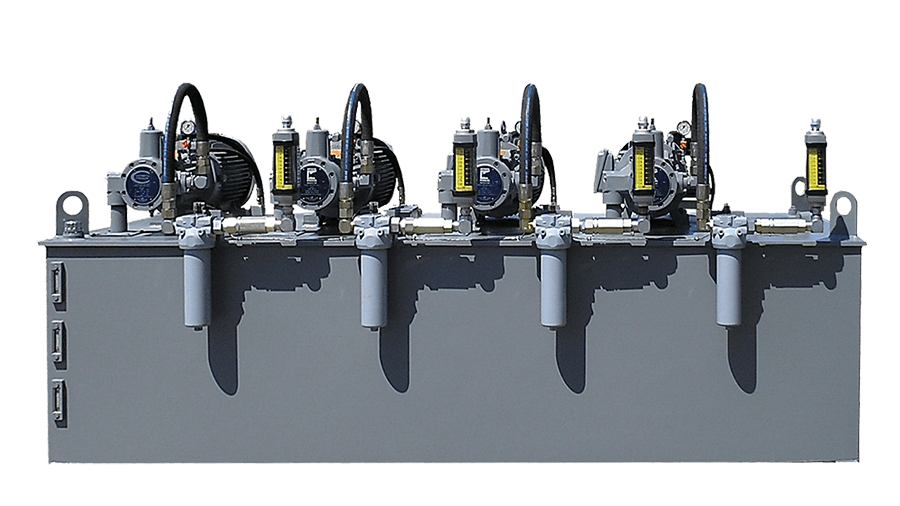
These are containers that can be attached to the hydraulic actuators. They collect water from the pumping mechanism and are intended to build and maintain fluid pressure to supplement the motor pumping system. Motor Pumps: A hydraulic power unit can be equipped with a single motor pump, or multiple devices each with their own accumulator valve. With a multiple pump system, usually only one operates at a time.
A hydraulic power unit can be equipped with a single motor pump, or multiple devices each with their own accumulator valve. With a multiple pump system, usually only one operates at a time. Tanks: The tank is a storage unit designed with enough volume for the fluid in the pipes to drain into it. Likewise, actuator fluid may sometimes need draining into the tank.
The tank is a storage unit designed with enough volume for the fluid in the pipes to drain into it. Likewise, actuator fluid may sometimes need draining into the tank. Filters: A filter is typically installed along the top of the tank. It is a self-contained bypass unit, with its own motor, pump, and filtering apparatus. It can be used to fill or empty the tank by activating a multi-directional valve. Because they are self-contained, filters can often be replaced while the power unit is functioning.
A filter is typically installed along the top of the tank. It is a self-contained bypass unit, with its own motor, pump, and filtering apparatus. It can be used to fill or empty the tank by activating a multi-directional valve. Because they are self-contained, filters can often be replaced while the power unit is functioning. Coolers and Heaters: As part of the temperature regulation process, an air cooler can be installed near or behind the filter unit to prevent temperatures from rising above operational parameters. Likewise, a heating system, such as an oil-based heater, can be used to elevate temperatures when necessary.
As part of the temperature regulation process, an air cooler can be installed near or behind the filter unit to prevent temperatures from rising above operational parameters. Likewise, a heating system, such as an oil-based heater, can be used to elevate temperatures when necessary. Power Unit Controllers: The hydraulic controller unit is the operator interface containing power switches, displays, and monitoring features. It is necessary for installing and integrating a power unit into a hydraulic systems, and can usually be found wired into the power unit.
How to Select Hydraulic Power Motors
The power source, or prime mover, associated with most hydraulic power units is the motor, which is generally selected based on its speed, torque level, and power capacity. A motor whose size and capabilities complement those of the hydraulic power unit can minimize wasted energy and raise cost-efficiency in the long-term.
The criteria for motor selection vary according to the type of power source being employed. For example, an electric motor has an initial torque much greater than its operating torque, but diesel and gasoline-powered motors have a more even torque-to-speed curve, delivering a relatively steady amount of torque at both high and low running speeds. Consequently, an internal combustion engine may be able to initiate a loaded pump, but not provide enough power to bring it to operating speed if it is not properly matched with the hydraulic power unit.
Motor Size
As a rule of thumb, the power rating for a diesel or gasoline motor used with a hydraulic power unit needs to be at least double that of an electric motor suitable for the same system. However, the cost of the electricity consumed by an electric motor over its operational lifespan usually outstrips the cost of the motor itself, making it important to find an appropriately sized unit that will not waste energy consumption. If the pumping pressure and liquid flow are set at a constant rate, motor size can be measured according to the following parameters:
• Horsepower
• Gallons per minute
• Pressure, measured in pounds per square inch (psi)
• Mechanical pumping efficiency
In some cases, the hydraulic system may require different levels of pressure at various stages of the pumping process, meaning that horsepower can be calculated as the root mean square (rms) and a smaller motor may suffice for the project. However, the motor must still be able to meet the torque requirement for the highest pressure level in the cycle. Once the rms and the maximum torque (including initial and operational levels) have been calculated, they can be cross-referenced with a motor manufacturer’s performance charts to determine whether the motor is the necessary size.
Electric Motor Power
Electric motors and internal combustion motors, such as diesel or gasoline engines, exhibit different torque characteristics that dictate their varying power capacities. A typical three-phase electric motor begins its operating sequence by turning a rotor. When the rotor accelerates, the torque level drops slightly, then increases again when the rotation hits a specific rpm rate. This temporary drop is known as “pull-up torque,” while the maximum value is designated as “breakdown torque.” When the rotor speed surpasses the breakdown level, torque decreases steeply. An electric motor’s torque-to-speed curve remains roughly the same regardless of power capacity, and it is usually run at full-load speed but below the breakdown point to reduce any risk of stalling.
Gasoline and Diesel Motor Power
Internal combustion motors have a significantly different torque-to-speed curve with fewer torque fluctuations. Generally, diesel and gasoline motors have to operate at higher speeds to achieve the necessary torque to power a pump. A horsepower rating approximately two and a half times greater than that of an electric motor counterpart is typically required for an internal combustion engine to reach the torque levels needed for a hydraulic power unit. Manufacturers normally recommend that gasoline or diesel motors operate continuously at only a portion of their maximum rated power in order to prolong the motor’s lifespan, and keeping the torque below maximum level can often improve fuel efficiency.
Operating Process of Hydraulic Power Units
When a hydraulic power unit begins functioning, the gear pump pulls hydraulic fluid out of the tank and moves it into an accumulator. This process continues until the pressure within the accumulator reaches a predetermined level, at which point a charging valve switches the pumping action to begin circulating fluid. This causes the pump to release fluid through a charging valve back into the tank at minimal pressure. A special one-way valve keeps fluid from flowing out of the accumulator, but if the pressure drops by a significant amount, the charging valve reactivates and the accumulator is refilled with fluid. Farther down the line, a reduced-pressure valve regulates the flow of oil moving to the actuators.
If the accumulator is equipped with a fast-stroking device, it can be connected to other accumulators to allow them to charge pressure as well. Often, an automatic thermostat or fan will be included to help alleviate rising temperatures. If the fluid in the system begins to overheat, a temperature switch can shut the motor-pump off, which can also help refill the tank if its fluid level is too low. If the hydraulic power unit has multiple motor pumps, a flow switch can have them alternate in case of reduced fluid supply. Pressure switches can be used to regulate accumulator pressure and a monitoring system can alert operators when pressure has dropped too low, elevating the risk of power unit failure.
Other Hydraulic Articles
More from Electrical & Power Generation
How Does a Hydraulic System Work? O-Seal Trusted by the Navy
/ How Does a Hydraulic System Work? O-Seal Trusted by the Navy
How Does a Hydraulic System Work? O-Seal Trusted by the Navy
Hydraulic systems can be found in everything from cars to industrial machinery. They’re designed to provide power, control, safety, and reliability, but how does a hydraulic system work?
How Does a Hydraulic System Work?
Hydraulic systems are made up of numerous parts:
The reservoir holds hydraulic fluid.
The hydraulic pump moves the liquid through the system and converts mechanical energy and motion into hydraulic fluid power.
The electric motor powers the hydraulic pump.
The valves control the flow of the liquid and relieve excessive pressure from the system if needed.
The hydraulic cylinder converts the hydraulic energy back into mechanical energy.
There are also numerous types of hydraulic systems, but each contains the same main components listed above. They’re also all designed to work the same way.
Hydraulic systems use the pump to push hydraulic fluid through the system to create fluid power. The fluid passes through the valves and flows to the cylinder where the hydraulic energy converts back into mechanical energy. The valves help to direct the flow of the liquid and relieve pressure when needed.
Hydraulic Systems on Ships
In addition to vehicles and industrial machinery, hydraulic systems can be found on ships. Hydraulic systems on ships are used in various applications. For example, systems used for cargo systems make carrying heavy materials and performing other cargo operations easier and less time consuming.
A ship’s engine room also includes hydraulic systems such as a hydraulic automatic control system. These help to regulate valve positions as well as the pneumatic air pressure in the engine room.
On top of that, hydraulic systems in a ship’s stabilizers prevent the vessel from rolling and ensure a smooth performance across open waters.
Plus many industrial ships include machinery and tools like deck cranes that are run by hydraulic systems.
O-Seal Valves and Fittings and the Navy
Hydraulic systems can be found on many US Navy vessels. And with help from CPV Manufacturing and our line of O-Seal valves and fittings, these systems can ensure smooth operations and safety.
Our line of O-Seal products was developed in the 1950s when CPV Manufacturing started working with the US Navy. We wanted to make sure that every component of our high-pressure couplings met US Navy specifications. However, testing each connection would have been too strenuous and dangerous to do by hand. That’s when we created a test stand using O-ring connections.
Contact The Valve Experts
This method allows us to easily disassemble and reassemble each component to perform each test to ensure proper performance and safety. We then took those concepts and developed our line of O-Seal products.
Benefits of O-Seal Valves and Fittings in Hydraulic Systems
CPV Manufacturing’s O-Seal valves and fittings are unique. Unlike other valves, our products are leakproof and designed to last. On top of that, they can withstand extreme temperatures and are rated for vacuum to 6,000 psi in liquid or gas applications, making them ideal for many types of hydraulic systems.
However, what makes our O-Seal valves truly unique is that they come with interchangeable parts. The soft goods in the cartridge can be removed and made with different types of materials for certain applications.
The versatility of our O-Seal products presents a cost-effective solution for the US Navy and many other companies across the globe. With interchangeable parts, our O-Seal valves can be used for a number of applications, which means companies no longer purchase additional valves to run their systems.
To learn more about our line of O-Seal products, contact CPV Manufacturing now.
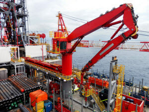
Hydraulic Power Control Units
IMI Remosa’s Hydraulic Power Control Units are designed in accordance with the most stringent process licensor specifications and international standards.
Actuators and Hydraulic Power Control Units are designed to provide the valve with the desired action. As standard, actuator, hydraulic power unit and control unit will consist of the following:
Actuator Mechanical Drive Section
Hydraulic piston Mechanical drive section case Manual drive Worm gear-motor Clamp lock assembly Manual drive engaging/disengaging system Adjustable limit stops Stem anti-rotation device Mechanical position indicator (double reference scale) Redundant position transmitters Valve closed position switch Pneumatic motor Lifting lugs
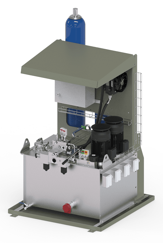
Hydraulic Power and Control Unit
Two electrical driven oil pumps: primary and stand-by Two hydraulic filters Hydraulic reservoir Main accumulators ESD accumulators Manual hydraulic operator Servo-valve manifold ESD circuit manifold All instrumentation, valves and piping necessary for Unit operation Cylinder isolation manifold Local (or remote) panel with a control system for alarm and monitoring signals data acquisition and position control, and a Human-Machine-Interface (HMI) for alarm and variable indications for all actuator and hydraulic power unit monitoring parameters Back-up control system (jog-control) Air/oil cooling/circulation and filtration system
Final configuration for actuator, hydraulic power unit and control unit could differ from the above description to comply with all the applicable project specifications.
The electro-hydraulic actuators are always designed in compliance with all the applicable project specifications. In details:
Actuator set components will be designed to support environmental temperatures during operation.
Stroking time from the fully-closed position to the 100% open position will be in accordance to project specifications. The actuator nominal thrust, as standard, is 200% over the required thrust.
Fail safe mode: according to valve data-sheet.
Main accumulators: hydraulic power accumulator, piston type, Viton® seals, to provide hydraulic fluid for a minimum of two full strokes based on maximum travel and normal operation thrust with a thrust safety factor of two.
Stand-by (ESD/Reserve) accumulators: hydraulic power accumulator, piston type, Viton® seals, to provide hydraulic fluid for a minimum of two full strokes based on maximum travel and normal operation thrust with a thrust safety factor of two.
Oil reservoir: is sized to provide enough capacity for two times all accumulators, cylinders, manifolds and piping.
Electrical pump: are sized to allow 10% of total stroke in 5/10 sec max once main accumulators have been disconnected.
Electrical motors will have corrosion protection.
Electrical power, climatic ambient temperature range, electrical and electronic classification: according to project specifications.
All electrical systems protection degree will be IPW-65.
Highly ergonomic design for HPCU and mechanical actuator is chosen by Remosa to allow easy operation and maintenance.
Operating modes
In hydraulic mode the double effect cylinder receives high pressurized oil from a port (C1 or C2), while the other port allows the oil discharge from the other side of cylinder. The differential pressure between the two hydraulic cylinder cameras generates the thrust required to move a valve disc.
To work in mechanical mode every hydraulic function needs to be disabled; it is also necessary to manually engage this mode in order to avoid any chance of hydraulic and mechanical contemporary use. The system engagement is made by rotating the engaging lever; once rotated, two bronze split nuts clamp an ISO screwed bar and the clamp lock assembly starts moving according to the screw rotation.
Once engaged the mechanical drive, the field operator can manouver the actuator by a rotation of the actuator handwheel or by the pneumatic motor.
The worm gear-motor will run in lubricant medium and will be sealed by Viton® type material seals.
Hydraulic design features
All the main components (HPCU frame, oil reservoir, valves, etc) are manufactured on stainless steel SS304L or SS316L.
Pipe, pipe fittings and isolation valves will be flanged or socket welded constructed in 316L SS, with size and schedule suiting the system design pressure.
All pressure instruments are provided with block and bleed manifold. All electronic transmitters (pressure, differential pressure, temperature and level) are Hart 4-20mA output type: discharge pump A pressure transmitter, discharge pump B pressure transmitter, filters differential pressure transmitter, main accumulator pressure transmitter, oil reservoir level transmitter, oil reservoir temperature transmitter, cylinder close side pressure transmitter, cylinder open side pressure transmitter, lock-in-place test pressure transmitter.
Two variable displacement, axial pistons hydraulic pumps are provided. Each pump is provided with pressure transmitters at discharge side and a pressure transmitter downstream the hydraulic filters to monitor main hydraulic system pressure.
Standby pump starts up automatically in case of main pump failure. Interlock is provided to prevent pump and air cooling system operation in the event of no hydraulic fluid in the reservoir. A skid grounding system has always provided.
Electrical motors (provided) are certified according to project specifications.
An air-oil cooling system is installed to allow an oil temperature control during operation.
Hydraulic filters are designed for the full differential pressure of the pump discharge. A differential pressure indicator and alarm is supplied across the filters. Changing filter elements does not result in a loss of main hydraulic fluid system pressure.
All accumulators are provided with isolation and bleed valves. Bleed valves are permanently connected to the reservoir.
The hydraulic reservoir is provided with a thermometer, temperature transmitter, level gauge and level transmitter. Drain valve and provision for clean out are provided on the oil reservoir.
To allow for manual hydraulic operation, a manually operated shutoff valve to isolate the servo-valve from the hydraulic system and close the pilot operated check valves (POCV), and a manually operated 3-position valve (open-auto-close) are provided.
IMI Remosa installs jet-pipe style servo-valve, the best available in the market for this critical application, less sensitive to dirt than standard nozzle/flapper style servo-valve. The servo-valve can be isolated and removed for repair without depressurizing the hydraulic system.
Electronic design features
Position control is implemented in the digital control system and fulfils the following performance requirements:
Input and output signals: 4-20 mA, DC Valve closed: 4 mA Valve opened: 20 mA Stroking requirements: adjustable speed Design stroke: according to project specifications Design speed: according to project specifications ESD speed: according to project specifications Continuous: 10% of stroke in 5/10 seconds (for pump sizing only) Step resolution, dynamic response, dead band, transient overshoot, stability, repeatability, linearity in compliance with the requirements of project technical specifications.
Cable interconnection between field instruments and the local (or remote) control system are accomplished by means of a dedicated terminal strip, properly located, and with available space to allow easy access of maintenance personnel. The terminal strip are also mechanically designed to allow easy connection, disconnection and handling of cables in the field.
All signals related to lock in position logic (Low low main hydraulic system pressure, HPU instrument power loss, electronic failure, manual gear mode selected, hand-wheel engaged, position signal failure and control signal failure) lock the valves in last position (high deviation alarm as standard is not a lock in position cause).
IMI Remosa installs as standard a local operator interface for field operation. The local panel is certified according to the area classification of the unit. Local panel incorporates protections against rain and dust exposure according to IP-65 code. All alarms/shutdown indications, auxiliary and monitoring systems variables are available on the local panel.
Actuator trouble alarms configured at local panel include:
Loss of control signal
Loss of tracking (deviation alarm)
Position signal failure
Power supply failure
Hydraulic system trouble alarms configured at local panel include:
Low pressure at pump A discharge
Low pressure at pump B discharge
Low low level at reservoir
High high temperature of hydraulic oil
High differential pressure at filters
Low pressure at main accumulator
The following indications are also configured at local panel:
Slide valve position
Position control signal output
“Hand-wheel engaged”
Pumps running
All indications from transmitters specified for the actuator system
A local digital control system (with serial link to the DCS, i.e. Modbus-RTU via RS-485) is provided for the actuator sub-system variables data acquisition, alarm handling, position control and drive automatic start-up of stand-by equipment.
All control and interlock signals are transmitted hardwired to DCS.
All the components, such as servo-valves, transmitters/transducers, limit switches, solenoid valves, are explosion proof Ex’d or intrinsically safe Ex’i or encapsulation Ex’m certified (and not components for safe area encapsulated in explosion proof housing).
So you have finished reading the how does a hydraulic power unit work topic article, if you find this article useful, please share it. Thank you very much. See more: hpu hydraulic power unit, How does a hydraulic press work, Hydraulic power unit, hydraulic power unit for sale, how does hydraulic power work, hydraulic power unit components, industrial hydraulic power unit, hydraulic power unit wikipedia