
You are looking for information, articles, knowledge about the topic nail salons open on sunday near me how to create a plane on a cylinder in solidworks on Google, you do not find the information you need! Here are the best content compiled and compiled by the Chewathai27.com team, along with other related topics such as: how to create a plane on a cylinder in solidworks how to make a reference plane at an angle in solidworks, how to rotate a reference plane in solidworks, how to cut a cylinder in solidworks, how to add a sketch plane in solidworks, how to offset plane in solidworks, how to change plane in solidworks, how to make a perpendicular plane in solidworks, how to wrap text in solidworks
Contents
How do you make a plane in Solidworks?
To create an offset plane, select the Reference Geometry drop down on the CommandManager and choose the Plane option. Once the option to create a plane is open, select a face or another plane and set a distance for the offset.
How do you model a cylinder in Solidworks?
- Click Solids > Draw > Cylinder (or type Cylinder).
- Set an option for the cylinder’s base: …
- Click in the graphics area or type values to specify the cylinder height. …
- – or –
- If you want the center of the top face of the cylinder to lie somewhere else, enter the Center of other end option.
How do I add a reference plane in Solidworks?
Select the Insert> Reference Geometry > Plane from the top menu options. Option 3: With our default planes shown, holding CRTL, selecting the screen boarder of an existing plane and dragging a new plane into the model space.
How do you create a front plane in Solidworks?
Select the sketch in the FeatureManager design tree, and click Edit, Sketch Plane. Right-click the sketch in the FeatureManager design tree, and select Edit Sketch Plane . Select a new plane in the FeatureManager design tree or select a new planar face in the model for Sketch Plane/Face . Click OK .
How do you make a reference plane?
- On the ribbon, click (Reference Plane). Architecture tab Work Plane panel (Reference Plane) Structure tab Work Plane panel (Reference Plane) …
- To draw a line: On the Draw panel, click (Line). …
- To pick an existing line: On the Draw panel, click (Pick Lines).
How do you add a sketch plane in Solidworks?
- Click Plane (Sketch toolbar) or Tools > Sketch Entities > Plane to display the Sketch Plane PropertyManager. …
- From the FeatureManager design tree, select a plane, and click 3D Sketch on Plane (Sketch toolbar) or Insert > 3D Sketch on Plane.
How do you make a hollow cylinder on shape?
- Tap Shell tool.
- Optionally, toggle Hollow to shell (hollow) the part without removing any faces.
- Select Faces to remove. …
- Specify Shell thickness. …
- Optionally, toggle to switch to the Opposite direction.
- Tap the checkmark.
How do you Draw a hollow cylinder in Solidworks?
- Click Solid > Create > Create Sketch .
- Select the XZ plane to sketch on. …
- Click Sketch > Create > Center Diameter Circle .
- Hover over the origin (or center) of the sketch. …
- Click once to begin placing the circle.
- Drag the mouse away from the center to start sketching a circle. …
- Click again to complete the circle.
How do you make a conical cut in Solidworks?
- Click Solids > Draw > Cone (or type Cone).
- Set an option for the cone’s base: Center point base: Click in the graphics area to specify a center point or type the 3D coordinates. Click in the graphics area or type a value for radius. …
- Set the cone height: Click in the graphics area or type a value. – or –
How do you add a plane?
Click Plane (Reference Geometry toolbar) or Insert > Reference Geometry > Plane . The software creates the most likely plane based on the entity you select. You can select options under First Reference, such as Parallel, Perpendicular, and so forth to modify the plane.
What is front plane in SolidWorks?
SolidWorks provides Front, Top, and Right planes as defaults. The orientations (Front, Top, Right, and so on) relate to these planes. Planes are used for sketching and for creating geometry for features. You can create reference planes in addition to the default planes, and you can open sketches on planar model faces.
How do you create a plane in SOLIDWORKS 2019?
Click Plane (Reference Geometry toolbar) or Insert > Reference Geometry > Plane . The software creates the most likely plane based on the entity you select. You can select options under First Reference, such as Parallel, Perpendicular, and so forth to modify the plane.
How do you make a reference plane?
- On the ribbon, click (Reference Plane). Architecture tab Work Plane panel (Reference Plane) Structure tab Work Plane panel (Reference Plane) …
- To draw a line: On the Draw panel, click (Line). …
- To pick an existing line: On the Draw panel, click (Pick Lines).
How do you project geometry in SOLIDWORKS?
Click Project Curve on the Curves toolbar, or Insert > Curve > Projected. Use this selection to project a sketched curve onto a model face. Under Sketch to Project , select the curve in the graphics area or from the flyout FeatureManager design tree.
How do I create a new sketch in SOLIDWORKS?
- Click a sketch tool on the Sketch toolbar, such as Rectangle. .
- Click Sketch. on the Sketch toolbar, or click Insert > Sketch.
Creating Reference Planes in SOLIDWORKS: Offset, Angle, Mid, & Cylindrical Surface | GoEngineer
- Article author: www.goengineer.com
- Reviews from users: 12366
 Ratings
 - Top rated: 3.5
- Lowest rated: 1
- Summary of article content: Articles about Creating Reference Planes in SOLIDWORKS: Offset, Angle, Mid, & Cylindrical Surface | GoEngineer Updating …
- Most searched keywords: Whether you are looking for Creating Reference Planes in SOLIDWORKS: Offset, Angle, Mid, & Cylindrical Surface | GoEngineer Updating In this tutorial, we explain how to create four different reference planes in SOLIDWORKS: offset, angle, mid, and cylindrical surface planes.
- Table of Contents:
Offset Planes
Angle Planes
Mid Planes
Cylindrical Surface Planes
More SOLIDWORKS Tutorials
Creating Angled Planes in SOLIDWORKS – YouTube
- Article author: www.youtube.com
- Reviews from users: 37444 Ratings
- Top rated: 3.0
- Lowest rated: 1
- Summary of article content: Articles about Creating Angled Planes in SOLIDWORKS – YouTube Updating …
- Most searched keywords: Whether you are looking for Creating Angled Planes in SOLIDWORKS – YouTube Updating Learn how to create angled planes in SOLIDWORKS using an axis and a plane, as well as how the options coincident and project can effect the sketch origin ori…solidworks, solidworks 3d cad, 3d cad, 3d modeling, 3d design
- Table of Contents:

Creating Cylinders – 2019 – DraftSight Help
- Article author: help.solidworks.com
- Reviews from users: 32830 Ratings
- Top rated: 3.9
- Lowest rated: 1
- Summary of article content: Articles about
Creating Cylinders – 2019 – DraftSight Help
Updating …
- Most searched keywords: Whether you are looking for
Creating Cylinders – 2019 – DraftSight Help
Updating
- Table of Contents:
Creating Cylinders – 2019 – DraftSight Help
How to Create Reference Planes in SOLIDWORKS
- Article author: blog.alignex.com
- Reviews from users: 9187 Ratings
- Top rated: 3.3
- Lowest rated: 1
- Summary of article content: Articles about How to Create Reference Planes in SOLIDWORKS Updating …
- Most searched keywords: Whether you are looking for How to Create Reference Planes in SOLIDWORKS Updating Follow this step by step walk-through to learn how to create reference planes in SOLIDWORKS
- Table of Contents:

how to draw a plane in the centre of the hole or cylinder in solidworks? | GrabCAD Questions
- Article author: grabcad.com
- Reviews from users: 4642 Ratings
- Top rated: 4.9
- Lowest rated: 1
- Summary of article content: Articles about how to draw a plane in the centre of the hole or cylinder in solidworks? | GrabCAD Questions 1). Select “Plane” from “Reference Geometry” in “Features” Bar. 2). Click on cylinder one se cross section face. 3 … …
- Most searched keywords: Whether you are looking for how to draw a plane in the centre of the hole or cylinder in solidworks? | GrabCAD Questions 1). Select “Plane” from “Reference Geometry” in “Features” Bar. 2). Click on cylinder one se cross section face. 3 … how to draw a plane in the centre of the hole or cylinder in solidworks?
- Table of Contents:
Creating Reference Planes in SOLIDWORKS: Offset, Angle, Mid, & Cylindrical Surface | GoEngineer
- Article author: www.goengineer.com
- Reviews from users: 24192 Ratings
- Top rated: 3.1
- Lowest rated: 1
- Summary of article content: Articles about Creating Reference Planes in SOLIDWORKS: Offset, Angle, Mid, & Cylindrical Surface | GoEngineer In this tutorial, we explain how to create four different reference planes in SOLIDWORKS: offset, angle, m, and cylindrical surface … …
- Most searched keywords: Whether you are looking for Creating Reference Planes in SOLIDWORKS: Offset, Angle, Mid, & Cylindrical Surface | GoEngineer In this tutorial, we explain how to create four different reference planes in SOLIDWORKS: offset, angle, m, and cylindrical surface … In this tutorial, we explain how to create four different reference planes in SOLIDWORKS: offset, angle, mid, and cylindrical surface planes.
- Table of Contents:
Offset Planes
Angle Planes
Mid Planes
Cylindrical Surface Planes
More SOLIDWORKS Tutorials
Creating Planes – 2018 – SOLIDWORKS Help
- Article author: help.solidworks.com
- Reviews from users: 22888 Ratings
- Top rated: 3.8
- Lowest rated: 1
- Summary of article content: Articles about
Creating Planes – 2018 – SOLIDWORKS Help
You can use planes to sketch, to create a section view of a model, for a neutral plane in a draft feature, and so on. Click Plane (Reference Geometry toolbar) … …
- Most searched keywords: Whether you are looking for
Creating Planes – 2018 – SOLIDWORKS Help
You can use planes to sketch, to create a section view of a model, for a neutral plane in a draft feature, and so on. Click Plane (Reference Geometry toolbar) …
- Table of Contents:
Creating Planes – 2018 – SOLIDWORKS Help
Creating Planes in Solidworks – Illustrated Expression
- Article author: mechanicalland.com
- Reviews from users: 48535 Ratings
- Top rated: 4.4
- Lowest rated: 1
- Summary of article content: Articles about Creating Planes in Solidworks – Illustrated Expression Click to see how to create planes effectively in Solworks. … selected two faces of the cylinder as shown above, and a plane is created mdle of them. …
- Most searched keywords: Whether you are looking for Creating Planes in Solidworks – Illustrated Expression Click to see how to create planes effectively in Solworks. … selected two faces of the cylinder as shown above, and a plane is created mdle of them. How to use the Plane command in Solidworks? Click to see how to create planes effectively in Solidworks. It is very easy to do.
- Table of Contents:
How to Create Planes in Solidworks
How to Use Plane Command in Solidworks
Conclusion

Basics of SOLIDWORKS Reference Geometry: Planes |Basics of SOLIDWORKS Reference Geometry: Planes
- Article author: www.cati.com
- Reviews from users: 8559 Ratings
- Top rated: 3.7
- Lowest rated: 1
- Summary of article content: Articles about Basics of SOLIDWORKS Reference Geometry: Planes |Basics of SOLIDWORKS Reference Geometry: Planes This will create a plane tangent to the cylindrical face and parallel to the planar face. Tangent and Perpendicular. Similarly, if you choose a … …
- Most searched keywords: Whether you are looking for Basics of SOLIDWORKS Reference Geometry: Planes |Basics of SOLIDWORKS Reference Geometry: Planes This will create a plane tangent to the cylindrical face and parallel to the planar face. Tangent and Perpendicular. Similarly, if you choose a … In this blog, we will discuss the many ways of creating and defining Reference Planes if you need to use planes other than the default Top, Right, and Front Planes.|In this blog, we will discuss the many ways of creating and defining Reference Planes if you need to use planes other than the default Top, Right, and Front Planes.
- Table of Contents:

See more articles in the same category here: https://chewathai27.com/toplist.
Creating Reference Planes in SOLIDWORKS: Offset, Angle, Mid, & Cylindrical Surface
In this tutorial, we explain how to create four different reference planes in SOLIDWORKS:
Offset Planes
Angle Planes
Mid Planes
Cylindrical Surface Planes
Offset Planes
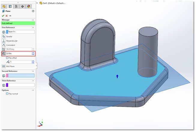
The most common type of reference plane is an offset plane. To create an offset plane, select the Reference Geometry drop down on the CommandManager and choose the Plane option.
Once the option to create a plane is open, select a face or another plane and set a distance for the offset. (Figure 1 & 2) There is also the option to create multiple planes when making an offset plane (Figure 3). When creating multiple planes this way, all of the planes created will have the same offset from each other.
(Figure 1)
(Figure 2)
(Figure 3)
Angle Planes
To create an angle plane, you’ll need a face and an axis line to angle about.
The axis line can be a model edge or a sketch line. (Figure 4) By default, the angle of the new plane will be perpendicular to the selected face/plane but you can change the angle at which the plane is offset from the selected face.
(Figure 4)
Multiple angle planes can be created at the same time; each being offset from the next by the selected angle. (Figure 5)
(Figure 5)
Mid Planes
When two faces are selected, a mid plane is created by default. The selected faces are not required to be parallel (Figure 6). If they are parallel, the resulting plane will be parallel and halfway between them. If not, the plane will be positioned between the two faces. A common use of this type of plane would be to create a mirror plane in the center of the part.
(Figure 6)
Cylindrical Surface Planes
Planes on cylindrical surfaces can get confusing because they often need more selections in order to finalize the plane. For example, if a cylinder and a plane are selected, the plane will rotate about the cylindrical face as the angle is adjusted. (Figure 7) Or, if multiple cylindrical faces are selected, a plane will be added that is tangent to both.
(Figure 7)
(Figure 8)
(Figure 9)
In either case, selecting the Flip option will let you set which side of the respective cylinder is used as the reference. (Figure 8 & 9)
I hope you found this article helpful. To learn more about SOLIDWORKS, check out more tips and tricks below.
More SOLIDWORKS Tutorials
Smart Explode Lines in SOLIDWORKS Explained
2 Ways to Reference a Cross-Section in SOLIDWORKS
Creating and Adding Weld Beads in SOLIDWORKS Models & Drawings
Record a Basic SOLIDWORKS Macro
Favorite SOLIDWORKS Tips from Tech Support
VIEW ALL SOLIDWORKS TUTORIALS
Creating Cylinders
Creating Cylinders
Use the Cylinder command to create a solid 3D cylinder. The base of the cylinder is parallel to the XY-plane of the coordinate system. The height is perpendicular to the base and parallel to the Z-axis.
To create a cylinder:
Click Solids > Draw > Cylinder (or type Cylinder). Set an option for the cylinder’s base: Center point base: Click in the graphics area to specify a centerpoint or type the 3D coordinates. Click in the graphics area or type a value for radius. The distance between the center point and the point picked is used for the radius. – or – Enter the Diameter option, then click in the graphics area or type a value for diameter.
3-point base (with a base that runs through the 3 points): Enter the 3Point option. Click in the graphics area or type values to specify the 3 points. The order in which you enter the points is arbitrary.
2-point diameter base (with two points that define the diameter and position of the cylinder): Enter the 2Point option. Click in the graphics area or type values to specify the first and second endpoints of the diameter.
Tangent, tangent, radius (TTR) base: Enter the TTR option. Select a point on a circle, arc, or line for the first and second tangents. Click in the graphics area or type a value for radius.
Tangent, tangent, tangent (TTT) base: Enter the TTT option. Select a point on a circle, arc, or line for the first, second, and third tangents.
Elliptical base: Enter the Elliptical option. Click in the graphics area or type values to specify the axis endpoints and the length of the other axis. – or – Enter the Center option, then (instead of defining the two endpoints of the ellipse axis) enter the center point of the axis followed by the length of the major and minor axis. Then click in the graphics area or type values to specify the center point, axis endpoint, and other axis.
Click in the graphics area or type values to specify the cylinder height. When you specify a height, the top center point is directly above the base center point along the Z-axis. – or – If you want the center of the top face of the cylinder to lie somewhere else, enter the Center of other end option. Click in the graphics area or type a value to specify a 3D point for the center point of the top face.
Access
Command: Cylinder
Menu: Solids > Draw > Cylinder
How to Create Reference Planes in SOLIDWORKS
By now we are all familiar with using the default Reference Planes (Front, Top & Right) within SOLIDWORKS. Whether being used to start a sketch or mating parts with assemblies, the use of reference planes is a fundamental building block of SOLIDWORKS Part Design or Assembly Modeling. So, what if we need a plane in a different location, possibly at an angle or offset at a given distance from the default Reference Planes?
In this blog, we will explain the different options for inserting references planes into our part or assembly models within SOLIDWORKS.
Accessing the Plane Wizard
Option 1:
Select Features > Reference Geometry > Plane on the command manager
Option 2:
Select the Insert> Reference Geometry > Plane from the top menu options.
Option 3:
With our default planes shown, holding CRTL, selecting the screen boarder of an existing plane and dragging a new plane into the model space.
Selecting Reference Items:
Now that the Planes Property Manager is displayed, we can see that we have the option to select up to three reference objects. A few examples of reference items include a Face, Line, Vertex, Axis, Point, and Plane.
Property Manager Options:
Once selecting an object to use for reference, we are given new options for how we would like to orientate the new plane relative to our First Reference selection.
As we continue to select Reference object’s, additional menu options become available.
Although we have the option to use up to three separate objects for reference, the majority of reference plane will be created from a single or possibly two references.
The next time you find yourself looking for a new location to create a sketch, inserting a feature not associated with the main body of your existing part, or adding additional constraints when Mating your assembly, try inserting a new Reference Plane into your model.
Do you have a unique method for inserting reference plane? Let us know in the comments below!
Thanks for checking out the Alignex blog! Make sure to subscribe down below to have content like this delivered straight to your inbox!
So you have finished reading the how to create a plane on a cylinder in solidworks topic article, if you find this article useful, please share it. Thank you very much. See more: how to make a reference plane at an angle in solidworks, how to rotate a reference plane in solidworks, how to cut a cylinder in solidworks, how to add a sketch plane in solidworks, how to offset plane in solidworks, how to change plane in solidworks, how to make a perpendicular plane in solidworks, how to wrap text in solidworks