
You are looking for information, articles, knowledge about the topic nail salons open on sunday near me how to wire a gm alternator on a tractor on Google, you do not find the information you need! Here are the best content compiled and compiled by the https://chewathai27.com team, along with other related topics such as: how to wire a gm alternator on a tractor delco remy 3-wire alternator wiring diagram, one wire alternator gm, how to wire a one wire alternator on a tractor, gm one wire alternator conversion kit, how to wire a alternator, 1 wire alternator conversion kit, gm 1 wire alternator 200 amp, one wire alternator problems
Contents
How do you wire a 3 wire alternator on a Ford tractor?
- Disconnect The Negative Terminal From The Tractor Battery. …
- Fabricate Mounting Brackets For The Alternator. …
- Connect The Output Bolt To The Positive Terminal Of The Battery. …
- Connect The Battery Negative Cable. …
- Disconnect The Battery Negative Terminal.
What are the 3 wires on a GM alternator?
Ans: The battery positive wire, the voltage sensor wire, and the ignition input wire are the three-wire types in a three-wire alternator wiring diagram. The positive wire from the battery is connected to the starter.
What wires go where on alternator?
Wiring Connections
Exciter wire is connected to the L terminal of an alternator and is used to turn on the voltage regulator. Excitor wire is needed to generate the voltage required for the alternator to start running. The positive and negative cables are small and connected to the respective terminals of the battery.
Does a one wire alternator need to be grounded?
Being a true one-wire alternator means that having a solid ground and an ample wire attached to the battery is all that you’ll need to keep that battery charged, and will do so with 100 amps output or more.
What are the two wires on a GM alternator?
The 10- and 12-SI units use a different two-wire connector plug on the rear of the alternator. The Number 1 wire on the 10- or 12-SI is connected to the charge warning light on the dash. The Number 2 wire is what is called the voltage sensing wire.
What is the difference between a 1 wire and a 3 wire alternator?
Striking a compromise between functionality and looks is a battle that can arise when it comes to choosing an alternator. While the 1-wire units offer clean and simple installation with minimally visible wiring, the OE-style 3-wire units can provide better electrical performance for the demands of your hot rod.
What is R terminal on alternator?
The “R” terminal or Relay terminal as it is sometimes called, provided some of the alternator’s output and was used to power electric tachometers, a dash light, hour meters, or other modern accessories. In some applications it was connected to the dash light to give notice if the alternator was failing to charge.
What is B on an alternator?
B terminal – Main alternator output terminal (connected to the battery) F terminal – Full-field bypass for regulator.
What are the terminals on an alternator?
Alternators usually have four terminals marked with letters. The “B” terminal is the main output which connects to the battery. The “S” terminal also connects to the battery and measures the voltage. The “IG” terminal is connected to the ignition switch, and the “L” terminal is connected the charging light.
What is R terminal on alternator?
The “R” terminal or Relay terminal as it is sometimes called, provided some of the alternator’s output and was used to power electric tachometers, a dash light, hour meters, or other modern accessories. In some applications it was connected to the dash light to give notice if the alternator was failing to charge.
What wire goes from alternator to battery?
The first thing you need to know is that there are generally three wires that need to be attached to your alternator: the positive (or “+”) terminal, the negative (or “-“) terminal, and the ground wire. The positive terminal is usually red, and it goes to the battery positive terminal.
How does a tractor alternator work?
Usually attached to the side or top of the engine and driven via a belt, the alternator chiefly consists of two windings of wire. Applying current to the inner coil (rotor) generates magnetism; when spun inside the outer coil of wire (stator) this generates a flow of electrical current.
3 Wire Alternator Hookup Explained- It’s Easy- If I Can Do It, So Can You! Bad Hombre Garage Ep. 88 – YouTube
- Article author: www.youtube.com
- Reviews from users: 35589
 Ratings
 - Top rated: 4.2
- Lowest rated: 1
- Summary of article content: Articles about 3 Wire Alternator Hookup Explained- It’s Easy- If I Can Do It, So Can You! Bad Hombre Garage Ep. 88 – YouTube Updating …
- Most searched keywords: Whether you are looking for 3 Wire Alternator Hookup Explained- It’s Easy- If I Can Do It, So Can You! Bad Hombre Garage Ep. 88 – YouTube Updating In this episode I replace the old externally regulated and unreliable 12 volt GM alternator with a remanufactured Delco 10si GM alternator. There were some …model a, hotrod, ratrod, rat rod, hot rod, build, rat rod build, hot rod how to, gm, alternator, generator, idiot light, wiring, dleco, delco, 10si, 12si, 3wire, 3 wire, 1 wire, hookup, hook-up, alternator hook up, willys, 12v, 12 volt, jeep, cj5, cj-5, f-134, f134, conversion, convert, roadkill, retro, Delhi, Delco, Charging, Automotive wiring, Hot rod garage, Ddspeedshop, Roadkill, Roadkill garage
- Table of Contents:

3 Wire Alternator Wiring Diagram 🏎️ What Wires Go Where?
- Article author: www.motorverso.com
- Reviews from users: 1662 Ratings
- Top rated: 3.6
- Lowest rated: 1
- Summary of article content: Articles about 3 Wire Alternator Wiring Diagram 🏎️ What Wires Go Where? Updating …
- Most searched keywords: Whether you are looking for 3 Wire Alternator Wiring Diagram 🏎️ What Wires Go Where? Updating A 3 wire alternator wiring diagram will teach you the fundamentals of the circuit and how the components are connected in a circuit.
- Table of Contents:
Overview Of 3 Wire Alternator Wiring Diagram
What Exactly Is An Alternator
What Is The Function Of The Alternator
Connections In A Wire Alternator Wiring Diagram
Wire Alternator Wiring Diagram
Why Is It Necessary To Use A 3 Wire Alternator Wiring Diagram
Wire Alternator Wiring Diagram And Function In A Car
How To Wire A Three Wire Alternator Wiring Diagram
FAQs – Wire Alternator Wiring Diagram
Final Verdict Wire Alternator Wiring Diagram
Approved Tools
Related News
Leave a Reply Cancel reply
Categories
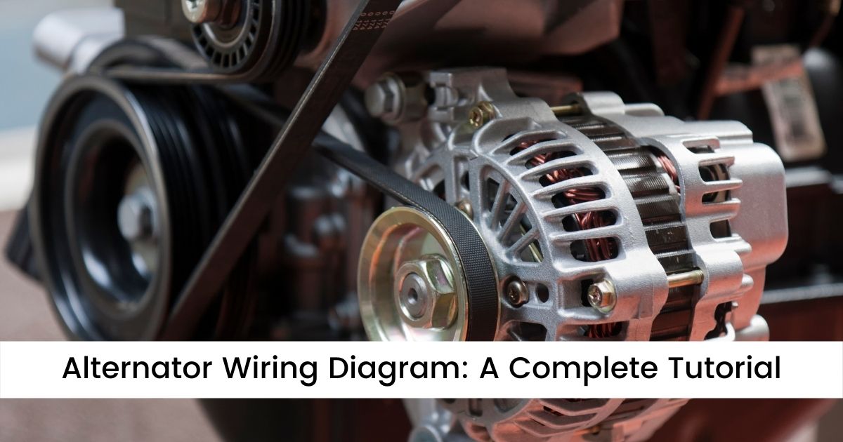
Alternator Wiring Diagram: A Complete Tutorial | EdrawMax
- Article author: www.edrawsoft.com
- Reviews from users: 10630 Ratings
- Top rated: 4.7
- Lowest rated: 1
- Summary of article content: Articles about Alternator Wiring Diagram: A Complete Tutorial | EdrawMax Updating …
- Most searched keywords: Whether you are looking for Alternator Wiring Diagram: A Complete Tutorial | EdrawMax Updating Alternator wiring diagrams are important to simplify the complex connections of an alternator. Use Edraw Max to create innovative and simple wiring diagrams in just a few clicks.
- Table of Contents:
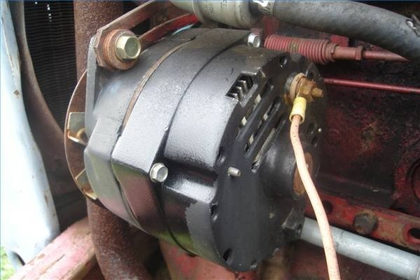
How to Wire an Alternator on a Tractor | It Still Runs
- Article author: itstillruns.com
- Reviews from users: 23241 Ratings
- Top rated: 4.4
- Lowest rated: 1
- Summary of article content: Articles about How to Wire an Alternator on a Tractor | It Still Runs Replacing the generator with a GM one-wire alternator is recommended. Step 1. Disconnect the negative terminal from the tractor battery. Step 2. …
- Most searched keywords: Whether you are looking for How to Wire an Alternator on a Tractor | It Still Runs Replacing the generator with a GM one-wire alternator is recommended. Step 1. Disconnect the negative terminal from the tractor battery. Step 2. One of the easiest and best improvements that can be made to an older tractor is to replace the original generator with an alternator. Alternators do a much better job at charging a battery at the low speed tractor engines are usually operated at. Replacing the generator with a GM one-wire alternator is recommended.
- Table of Contents:
How do you install a one wire alternator on a tractor? – TheKnowledgeBurrow.com
- Article author: theknowledgeburrow.com
- Reviews from users: 3643 Ratings
- Top rated: 3.5
- Lowest rated: 1
- Summary of article content: Articles about How do you install a one wire alternator on a tractor? – TheKnowledgeBurrow.com 2 How do you wire a tractor alternator? … How to Install a 1-Wire GM Alternator … Disconnect The Negative Terminal From The Tractor Battery. …
- Most searched keywords: Whether you are looking for How do you install a one wire alternator on a tractor? – TheKnowledgeBurrow.com 2 How do you wire a tractor alternator? … How to Install a 1-Wire GM Alternator … Disconnect The Negative Terminal From The Tractor Battery.
- Table of Contents:
How do you install a one wire alternator on a tractor
Can you wire alternator directly battery
How to install an alternator on a tuff battery
Post navigation
Viewing a thread – Wiring a GM 3 wire alternator
- Article author: talk.newagtalk.com
- Reviews from users: 44155 Ratings
- Top rated: 4.6
- Lowest rated: 1
- Summary of article content: Articles about Viewing a thread – Wiring a GM 3 wire alternator I am rewiring a gm alternator, and I am not sure how to wire it. … Most factory 12 V automotive and some tractor systems are wired to … …
- Most searched keywords: Whether you are looking for Viewing a thread – Wiring a GM 3 wire alternator I am rewiring a gm alternator, and I am not sure how to wire it. … Most factory 12 V automotive and some tractor systems are wired to …
- Table of Contents:
3 Wire Alternator Wiring Diagram 🏎️ What Wires Go Where?
- Article author: www.motorverso.com
- Reviews from users: 47672 Ratings
- Top rated: 4.8
- Lowest rated: 1
- Summary of article content: Articles about 3 Wire Alternator Wiring Diagram 🏎️ What Wires Go Where? Ans: Connect the positive cord to the positive terminal of the alternator. One cable connects to the starter motor, while the other connects to … …
- Most searched keywords: Whether you are looking for 3 Wire Alternator Wiring Diagram 🏎️ What Wires Go Where? Ans: Connect the positive cord to the positive terminal of the alternator. One cable connects to the starter motor, while the other connects to … A 3 wire alternator wiring diagram will teach you the fundamentals of the circuit and how the components are connected in a circuit.
- Table of Contents:
Overview Of 3 Wire Alternator Wiring Diagram
What Exactly Is An Alternator
What Is The Function Of The Alternator
Connections In A Wire Alternator Wiring Diagram
Wire Alternator Wiring Diagram
Why Is It Necessary To Use A 3 Wire Alternator Wiring Diagram
Wire Alternator Wiring Diagram And Function In A Car
How To Wire A Three Wire Alternator Wiring Diagram
FAQs – Wire Alternator Wiring Diagram
Final Verdict Wire Alternator Wiring Diagram
Approved Tools
Related News
Leave a Reply Cancel reply
Categories
Amazon.ca Something Went Wrong / Quelque chose s’est mal passé
- Article author: www.amazon.ca
- Reviews from users: 42571 Ratings
- Top rated: 4.5
- Lowest rated: 1
- Summary of article content: Articles about Amazon.ca Something Went Wrong / Quelque chose s’est mal passé New 12V 12 Volt Universal 1 Wire One Wire Alternator With 2 Grv Groove Pulley, Self Exciting Tractor, GM, Chevy & More in Alternators. …
- Most searched keywords: Whether you are looking for Amazon.ca Something Went Wrong / Quelque chose s’est mal passé New 12V 12 Volt Universal 1 Wire One Wire Alternator With 2 Grv Groove Pulley, Self Exciting Tractor, GM, Chevy & More in Alternators.
- Table of Contents:
See more articles in the same category here: 670+ tips for you.
3 Wire Alternator Wiring Diagram – What Wires Go Where?
A 3 wire alternator wiring diagram will show you the fundamentals of the circuit and how the various components are connected. The method of wiring a starter and alternator on an automobile is divided into two stages. Because starters consume and alternators produce large amounts of electricity, the first section focuses on power circuit connections.
The control circuits are involved in the second part. Starters and alternators are both controlled by their own control circuitry, which turns them on and off and regulates their output. The job is easier to understand, and the results are considerably more predictable when the wiring procedure is broken down into two groups.
When it comes to modernizing the electrical systems in their automobiles, we have a lot of options. A 1-wire or 3-wire alternator is one of such options. Initially, three-wire alternators were standard on most automobiles.
Let’s get into the details without further ado.
Overview Of 3 Wire Alternator Wiring Diagram
The 3 wire alternator wiring diagram has three electrical connections, as its name suggests. The large connector that connects to the battery is the first. The primary current flow charges the battery and drives the car when the engine is running. There are two smaller terminals on the top of the alternator, typically spade terminals.
The sense terminal is one of them. You must connect the alternator’s output to this terminal in order for it to sense and adjust the output voltage. The exciter is the opposite terminal. This is what energizes the alternator’s field. An alternator is a device that converts mechanical energy into electrical energy, and it’s especially useful in cars.
What Exactly Is An Alternator?
The alternator is the most critical component of a car’s engine and requires no maintenance. It creates electricity, serves as a power source for automobiles, and recharges the battery. The alternator converts mechanical energy to electrical energy by switching from alternating to direct current.
The major function of an alternator is to give electricity to electrical components such as lights, fans, and windshield wipers in conjunction with the battery. It converts alternating electricity to direct current and adjusts voltage to ensure that each unit receives the appropriate minimum power.
A cooling fan, rotor, slip ring end bearings, voltage regulator, stator, slip rings, carbon brushes, diode bridge rectifier, and pulley are all included in the alternator. The fundamental units for energy generation are the rotor and stator, while the rectifier aids in converting AC to DC.
All of the components work together to monitor and manage power so that different components of the car’s engine can get the energy they require. Because modern vehicles have so many different electrical components, a three-wire alternator wiring diagram is required to keep everything functioning smoothly.
An internal regulator in alternators monitors the number of volts going to the battery. Should the voltage suddenly rise or fall, the regulator will adjust the alternator’s output to maintain a constant flow of electricity to the battery. External regulators are used in single-wire alternators, which means the regulator may be replaced if it breaks. Mechanics must replace the complete alternator if the regulator fails or wears out in today’s alternator.
What Is The Function Of The Alternator?
An alternator works in a straightforward manner. An alternator is connected by a serpentine belt that rests on a pulley. The pulley moves and turns the rotor shafts attached to the alternator when the engine is started.
The rotor is an electromagnet with two spinning metal slip rings attached to its shaft, as well as carbon brushes. A little quantity of electricity is delivered to the rotor due to rotation, which is then transmitted to the stator.
The rotor’s magnets are positioned so that they pass through the stator’s copper wire loops. A magnetic field is created around the coils as a result of this. The magnetic field is altered when the rotor spins, and electricity is generated as a result.
However, because the electricity generated is AC, it must first be converted to DC before it can be used; therefore, it is routed through the alternator’s diode rectifier. The rectifier converts a two-way current into a one-way direct flow current. The voltage is then sent on to the voltage regulator, which adjusts the voltage to meet the needs of various car units.
Connections In A Wire Alternator Wiring Diagram
An alternator has a complicated wiring system because it is connected to many components. The exciter wire, as well as positive and negative wires, are the principal wirings. Exciter wire is used to turn on the voltage regulator and is linked to the L terminal of an alternator. Exciter wire is necessary to create the voltage required to start the alternator.
The positive and negative cables are small and connect to the battery’s positive and negative terminals. The alternator is also connected by the battery charging cable. It solely charges the battery and doesn’t provide power to any other devices. The ignition input wire from the alternator to the key switch is likewise connected to the alternator. The ignition wire activates the voltage regulator.
Wire Alternator Wiring Diagram
Here are several wire alternator wiring diagrams that can be utilized for a variety of applications. Let’s have a peek at their connections.
3 Wire Alternator Wiring Diagram
A three-wire alternator wiring diagram shows how the various components of a circuit are connected. The circuit is made up of three major wires: a positive cable for the battery, a voltage detecting wire, and an ignition wire. The engine is connected to the ignition input wire. The voltage detecting cable detects the voltage and connects to the rectifier, while the power wire delivers power from the engine to the alternator.
Multi-purpose alternators with built-in voltage rectifiers for power sensing are available. Unlike single-wire alternators, they may generate and rectify electricity in the same circuit. The use of a three-wire alternator wiring diagram guarantees that all components receive controlled voltage.
Electromechanical Voltage Regulator (External)
The voltage sensor cable is coiled into an electromagnet by electromechanical regulators. This creates a magnetic field around the magnet, which attracts the iron block. Cutout relays, regulators, and current regulators are all electromagnetic switches in such circuits.
The cutout relay connects the battery to the alternator, while the regulator and current regulator switch govern the voltage output of the alternator’s field circuit. Electromechanical circuits are necessary for AC stabilizing circuits; however, they are not employed in automobiles due to their inadequate relaying mechanism.
Diagram Of PCM-Controlled Wiring
Powertrain control module voltage regulation circuits are a form of alternator that uses internal modules to control the field circuit. The PCM regulates current flow by analyzing the body control module (BCM) data and determining a system’s charging requirements.
When the voltage falls below a certain threshold, the modules are activated, causing the current flow through the coil to modify its on-time. As a consequence, the system output is modified to accommodate the system’s requirements. The PCR-controlled alternators generate the appropriate voltages in a simple but effective manner.
Why Is It Necessary To Use A 3 Wire Alternator Wiring Diagram?
What’s crucial to note about the 3 wire alternator wiring diagram is that it can improve the electrical performance of your vehicle to meet your needs. A 3 wire alternator wiring diagram has three wires: the primary charge wire, a third wire that can jump between the regulator and the battery stud, and the exciter wire.
The 3 wire alternator wiring diagram is considerably less intrusive than it seems, as only two additional wires are integrated into the rest of the electrical system. Unless you are willing to rigorously manage your electrical budget when cruising at low RPM, the 3 wire alternator wiring diagram is recommended for improving your vehicle.
Wire Alternator Wiring Diagram And Function In A Car
The basic function of an alternator is to convert mechanical energy into electrical energy in an alternating manner. It is termed an alternator because it generates alternating current. The alternator function and wire alternator wiring diagram of an automobile are described in this article. We all know that an alternator is used to charge a car or an automobile. So, let’s get started.
The Function Of The Alternator In A Car
In an automobile, the alternator generates electrical energy to charge the battery. Initially, a car’s engine is started by a DC motor that draws power from the battery. As a result, there is a need to charge the battery.
The alternator is connected to the engine by a belt in an automobile. As a result, as the engine turns, the alternator rotates as well, producing alternating electrical energy. The automobile alternator contains some circuitry.
Wire Alternator Wiring Diagram
The three-wire alternator wiring diagram is used in the car, as you know that now. The stator and rotor are two elements of a three-wire alternator wiring diagram. The three-phase armature winding is found in the stator, while field winding is found in the rotor.
We know that batteries can only hold DC. As a result, a rectifier circuit is installed in the alternator, converting three-phase AC to DC. The field winding is connected to a voltage regulator circuit bypassing via the slip ring. The voltage regulator circuit receives the DC power source from the rectifier circuit’s output and distributes it to the field winding.
The voltage regulator circuit’s primary duty is to regulate the power input to the field winding. Assume the output voltage and current are boosted over their normal levels. The voltage regulator will reduce the power input to the field winding at this time, lowering the voltage in the armature winding and maintaining a normal value.
How To Wire A Three Wire Alternator Wiring Diagram?
You will know how simple it is to connect a new 3-wire alternator to update your old vehicle in the steps below. You’ll be done in no time if you stick to them.
1. Unplug the Negative Terminal of the Vehicle Battery
Remove the negative terminal from the vehicle battery before starting anything. This is not a difficult chore to complete. However, anything involving electricity or the vehicle battery should be approached with caution.
2. Assemble the Alternator Mounting Brackets
The second phase of your new endeavor could be the most difficult. But don’t worry, anything is achievable if you know how to do it correctly. It’s also worth noting that you might be able to find brackets in a junkyard that will work with minimal changes, which will save you money.
Another advantage is that you can make your own brackets out of 14-inch flat stock steel that is about 1 inch wide if you can’t find them in a junkyard. This is yet another wonderful approach to save money while still improving your old vehicle.
The brackets would then be mounted using the generator bracket’s original mounting holes in the engine block. It is critical to ensure that the pulleys are properly aligned for the belt and that the bracket allows for drive belt adjustment. After that, the alternator and new drive belt can be attached.
3. Connect the Positive Terminal Of The Battery To The Output Bolt
You’re halfway done, and you’ve already completed the most difficult portion. Connecting the output bolt on the back of the alternator to the positive terminal of the battery with 10-gauge wire and solderless ring terminals is the next step in enhancing your ancient automobile.
This connection can also be made on the starter solenoid, which is where the positive cable is connected. Then, connect the battery’s positive terminal to the starter solenoid.
4. Plug-In the Negative Battery Cable
Connecting the battery negative cable is the final step in upgrading your antique vehicle with a 3 wire alternator wiring diagram. You may improve the performance of your antique vehicle while also saving money by installing a 3-wire alternator.
The AC Delco 3 wire alternator wiring diagram is used in most GM products as well as various types of heavy equipment. This 3 wire alternator wiring diagram is remarkable in that it has a high output, a compact construction, and is simple to operate.
The required brackets can be used to convert this alternator to any vehicle or engine-powered equipment in just a few simple steps. To wire this alternator, you won’t need any special skills; anyone with average mechanical abilities should be able to do it.
5. Unplug the Battery’s Negative Terminal
The first step in wiring a 3 wire alternator wiring diagram to your vintage vehicle is to disconnect the battery negative terminal, as I explained in the preceding step-by-step guide. This is a crucial step that should not be skipped.
6. Connect The Wire To The Output Stud
The next step is to use a solderless ring connector to connect a piece of 10-gauge wire to the output stud on the rear of the alternator. The starter solenoid should be linked to the other end of this wire. Connecting it to the same terminal as the positive battery line requires simply a few simple steps.
7. Connect The Alternator Connector To The Receptacle Of The Alternator
The next step is to connect the new alternator connector to the receptacle on the alternator. It’s not difficult to solder a 14-gauge wire to the smaller pigtail from the connector. This wire connects to the IGN terminal on the ignition switch. Finally, connect a small 12-volt caution light in series with this cable in this step.
8. Splice A 10-Gauge Wire To The Bigger Wire On The Alternator Plug
Splicing a 10-gauge wire to the bigger wire on the alternator plug is one of the final stages in connecting an AC Delco 3-wire alternator to your vehicle. Connect the wires with a solderless connector to complete the procedure.
Make sure the wire is long enough to connect to the same starter solenoid terminal as the positive battery cable and the alternator output wire. Finally, use a solderless ring connection to attach the wire to the terminal. After this step, you’re practically done.
9. Putting The Final Touches On It
Connecting the battery negative terminal to the AC Delco 3 wire alternator wiring diagram is the final step in wiring it to your vehicle. After you’ve finished wiring, you’ll be able to utilize it and operate with ease.
Your vehicle will run more efficiently and be improved to a whole new level if you replace the old generator with a 3 wire alternator wiring diagram. Your enhanced vehicle will allow you to work more efficiently, which is every owner’s ultimate desire.
FAQs – Wire Alternator Wiring Diagram
What’s The Difference Between A One-Wire Alternator And A Three-Wire Alternator?
Ans: The 1-wire alternator only knows what it’s providing current to; the battery. The three-wire alternator detects the voltage at the fuse block and ignition, and the alternator will charge more to bring all of the systems up to power.
On An Alternator, What Are The Two Little Wires?
Ans: The positive and negative cables are the two wires that connect to the alternators. The alternator (S) terminal is connected to the (B+) circuit with a jumper wire.
What Does An Alternator’s Exciter Wire Do?
Ans: An alternator is a car component that transfers power from the fuel system to the battery, allowing vehicle accessories like the radio, headlights, and air conditioning fans to operate. When a car is started, an exciter wire generates the voltage required for the alternator to begin operating.
On A Wire Alternator Wiring Diagram, What Are The Three Terminals?
Ans: The battery positive wire, the voltage sensor wire, and the ignition input wire are the three-wire types in a three-wire alternator wiring diagram. The positive wire from the battery is connected to the starter. The voltage detecting wire is connected to the battery, while the ignition wire is connected to the key switch from the alternator.
With A Screwdriver, How Do You Inspect An Alternator?
Ans: Start your car by turning the ignition key to the “on” position. The voltage regulator is turned on, and the dashboard warning lights illuminate. Use the screwdriver to repeat the test. Place the screwdriver’s metal end towards the nut on the alternator pulley.
On An Alternator, What Do The Letters R And F Mean?
Ans: The ‘Reference’ or voltage sense terminal and the ‘Field’ terminal are the R and F terminals, respectively.
On A Wire Alternator Wiring Diagram, Which Wires Go Where?
Ans: Connect the positive cord to the positive terminal of the alternator. One cable connects to the starter motor, while the other connects to your battery if your alternator has two positive terminals. The two positive cables will be red and will be located nearby.
Where Should The Alternator Wire Be Connected?
Ans: This wire is either directly connected to the battery or via a connector in the main battery supply circuit. It usually connects to the fuse block’s battery side. Its job is to keep track of the system voltage and adjust the charging rate accordingly, based on the system load or battery status.
How Do You Connect An Alternator To A Battery Directly?
Ans: The main hub is connected to the battery through the “battery charging wire.” The battery charging line in these systems merely charges the battery and does not operate the electrical system. In many other autos, the alternator output line connects directly to the battery (or to the battery positive cable at the starter solenoid).
What Is The Best Way To Tell If My Alternator Has An Internal Regulator?
Ans: Look for a regulator under the washer bottle or a bracket on the radiator support’s driver side. It’s an internally regulated alternator if the pins are aligned like this “- -” on the side.
Final Verdict, Wire Alternator Wiring Diagram
Alternators are essential for keeping an automobile running once the engine has been started. Complex wiring is required for alternators, and the wires must be connected to the correct units and terminals. This can be simplified by designing alternator wiring schematics. Wire alternator wiring diagram shows how the connections and physical layout of a circuit are connected.
It’s easier to establish circuits and connect the alternator appropriately when you have a clear picture of each component’s wiring connections and position. It is vital to create circuits with adequate wiring to give each piece of equipment a proper voltage, ensuring that none is over or underpowered.
Approved Tools
These tools have been tried and tested by our team, they are ideal for fixing your car at home.
Alternator Wiring Diagram: A Complete Tutorial
Alternator Wiring Diagram: A Complete Tutorial Know it All about Alternator Wiring Diagram Twitter Share Copy Link copied!
You may not have heard the word alternator but you might be aware of the word alternating current or AC. Alternator allows you to convert mechanical energy into electrical energy especially in motor vehicles. An alternator wiring diagram will help you get the basic know-how of the circuit and how the components are linked together in a circuit. So, without further ado, let’s dive in.
What is an Alternator?
An alternator is a maintenance-free yet the most important unit of the car’s engine. It generates electricity and functions to provide electrical supply to cars and recharges the battery. The alternator works by converting mechanical energy into electrical energy from alternating current to the direct current.
The primary function of an alternator is to work jointly with the battery to supply energy to the electrical components, i.e., lights, fan, windshield wipers, etc. It changes the alternating current into a direct current and regulates the voltage to meet the required minimum power for each unit.
Source: samarins.com
The alternator comprises a cooling fan, voltage regulator, rotor, stator, diode bridge rectifier, slip rings, slip ring end bearings, carbon brushes, pulley. The rotor and stator are the central units for electricity generation, while the rectifier helps in converting AC to DC. All the components work jointly to monitor and regulate the power to match the energy needs of different components of the car’s engine.
Source: innovationdiscoveries.space
How Does the Alternator Work?
The functioning of an alternator is straightforward. A serpentine belt that rests on a pulley is attached with an alternator. When the engine is ignited, the pulley moves and rotates the rotor shafts attached to the alternator. The rotor is an electromagnet with two revolving metal slip rings and carbon brushes attached to its shaft. Due to the rotation, a small amount of electricity is supplied to the rotor, which is conducted to the stator.
The magnets on the rotor are placed in such a way that they pass over the copper wire loops in the stator. This creates a magnetic field around the coils. When the rotor spins, the magnetic field is disturbed, and this, as a result, generates electricity.
However, the current generated is AC has to be converted to DC before use; therefore, it is channeled to the alternator’s diode rectifier. The rectifier changes the two-way current into a one-way flow-direct current. The voltage then passes on to the voltage regulator that steps up or steps down the voltage to match the needs of different units of the car.
Wiring Connections
Since an alternator is connected to so many components, it exhibits a complex wiring system. The main wirings include the exciter wire, positive and negative cables. Exciter wire is connected to the L terminal of an alternator and is used to turn on the voltage regulator. Excitor wire is needed to generate the voltage required for the alternator to start running.
Source: blogspot.com
The positive and negative cables are small and connected to the respective terminals of the battery. The alternator also shows a connection with the ‘battery charging wire.’ It only charges the battery and does not supply energy to any other unit. The alternator also has an ignition input wire that is connected from the alternator to the key switch. The ignition wire turns on the voltage regulator.
Alternator Wiring Diagrams
Below given are some alternator wiring diagrams that are used for different purposes. Let’s have a look at their connections.
3 Wire Alternator Wiring Diagram
Source: www.carparts.com
This is a three-wire alternating wiring diagram showing the connections between the different components of a circuit. The circuit comprises three main wires: battery positive cable, voltage sensing wire, and ignition wire. The ignition input wire is attached to the engine. It conducts electricity from the engine to the alternator while the voltage detecting cable senses the voltage and is attached to the rectifier.
Such alternators are multi-purposed and have built-in voltage rectifiers for power sensing. Unlike the one-wire alternators, they can generate and rectify electricity in one circuit. Using a three-wire alternator ensures regulated voltage for all components.
External Electromechanical Voltage Regulator
Source: www.carparts.com
Electromechanical regulators coil the voltage sensing cable into an electromagnet. This creates a magnetic field around the magnet and attracts the ferrous block towards itself. Such circuits have three electromagnetic switches- cutout relays, regulator and, current regulator. The cutout relay connects the battery to the alternator while the regulator and current regulator switch regulate the voltage output by controlling the alternator’s field circuit.
The electromechanical circuits are important for the AC stabilizing circuits; however, they are not used in production vehicles due to their inefficient relaying system.
PCM Controlled Wiring Diagram
Source: www.carparts.com
The powertrain control module voltage regulation circuits are an advanced type of alternator that uses internal modules to control the field circuit of an alternator. The PCM regulates the current flow by examining the data from the body control module (BCM) and understanding the charging needs of a system.
Whenever the voltage is below the desired value, the modules are triggered, and it changes the on-time of current flow through the coil. As a result, the system output is changed to adjust the needs of the system. The PCR-controlled alternators are simple yet very efficient, generating the desired voltages.
Use EdrawMax for Wiring Diagram Creation
Alternators are very useful for keeping the car running when the engine is ignited. Alternators involve complex wiring, and the wires must be connected to the correct units and terminals. This can be simplified by creating alternator wiring diagrams.
Wiring diagrams provide a visual representation of the connections and physical layout of the circuit. With a clear visualization of each component’s wiring connections and position, it becomes easier to create circuits and connect the alternator correctly. Creating circuits with proper wiring is necessary to supply a proper voltage to each unit, so none gets over or underpowered.
Create wiring diagrams is simple and exciting if you have EdrawMax. EdrawMax is a user-friendly and innovative software that allows users to get creative and draw the most beautiful diagrams in just a few clicks. The software has a gamut of editing tools and a wide range of highly customizable symbol library that offers the freedom of creating whatever you want. Choose from the built-in templates or get innovative and design your own original diagrams from scratch. With an intuitive interface and extensive editing options, express your creativity and design helpful alternator wiring diagrams.
Related Articles
How to Wire an Alternator on a Tractor
Fabricate mounting brackets for your alternator. This is the hardest part of this project. You may be able to find brackets in a junkyard that will work with minor modifications. If brackets cannot be found you can make them yourself using 1/4-inch flat stock steel, about 1 inch wide. Mount the brackets using the original mounting holes in the engine block for the generator bracket. Make certain the pulleys align properly for the belt and that the bracket allows for adjustment of the drive belt. Install the alternator and new drive belt.
So you have finished reading the how to wire a gm alternator on a tractor topic article, if you find this article useful, please share it. Thank you very much. See more: delco remy 3-wire alternator wiring diagram, one wire alternator gm, how to wire a one wire alternator on a tractor, gm one wire alternator conversion kit, how to wire a alternator, 1 wire alternator conversion kit, gm 1 wire alternator 200 amp, one wire alternator problems