
You are looking for information, articles, knowledge about the topic nail salons open on sunday near me orcad 스위치 라이브러리 on Google, you do not find the information you need! Here are the best content compiled and compiled by the https://chewathai27.com/to team, along with other related topics such as: orcad 스위치 라이브러리 OrCAD 스위치 만들기, 피스파이스 스위치 라이브러리, PSpice SPDT Switch, Orcad dip switch library, 피스파이스 led 라이브러리, 피스파이스 스위치 사용법, PSpice 스위치 소자, PSpice 토글 스위치
:: OrCAD Tutorial
- Article author: instructables.tistory.com
- Reviews from users: 47948
 Ratings
 - Top rated: 3.9
- Lowest rated: 1
- Summary of article content: Articles about :: OrCAD Tutorial 아래 그림처럼 Library를 추가하고 부품을 찾으면 된다. Sw_tOpen, Sw_tClose 스위치는 라이브러리 검색이 잘 안된다. …
- Most searched keywords: Whether you are looking for :: OrCAD Tutorial 아래 그림처럼 Library를 추가하고 부품을 찾으면 된다. Sw_tOpen, Sw_tClose 스위치는 라이브러리 검색이 잘 안된다. Naver [OrCAD와 Psice] :: OrCad는 회로설계용으로 쓰이고 Pspice는 회로에 흘러가는 전압전류값을 분석하는 용도로 주로 쓰인다. [layout capacitor in cadence] 의뢰 페이지 링크(▶LINK) Capture 시작하기 ▼..
- Table of Contents:
OrCAD Tutorial
티스토리툴바

PSpice Model) SPDT 스위치 : 네이버 블로그
- Article author: m.blog.naver.com
- Reviews from users: 40044 Ratings
- Top rated: 4.6
- Lowest rated: 1
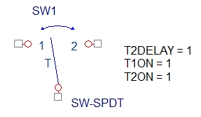
- Summary of article content: Articles about PSpice Model) SPDT 스위치 : 네이버 블로그 해당 모델의 이름 SW-SPDT 이며, 사용 시 Simulation Setting의 Configuration Files에 첨부된 Library 파일을 추가하셔야 시뮬레이션이 됩니다. 해당 … …
- Most searched keywords: Whether you are looking for PSpice Model) SPDT 스위치 : 네이버 블로그 해당 모델의 이름 SW-SPDT 이며, 사용 시 Simulation Setting의 Configuration Files에 첨부된 Library 파일을 추가하셔야 시뮬레이션이 됩니다. 해당 …
- Table of Contents:
카테고리 이동
행복찾기
이 블로그
PSpice
카테고리 글
카테고리
이 블로그
PSpice
카테고리 글
라이브러리에서 부품을 못찾겠어요. – 지식 게시판 – OrCAD and PSpice
- Article author: m.cafe.daum.net
- Reviews from users: 17509 Ratings
- Top rated: 4.6
- Lowest rated: 1
- Summary of article content: Articles about 라이브러리에서 부품을 못찾겠어요. – 지식 게시판 – OrCAD and PSpice 포토커플러랑 딥스위치인데 이게 기본 라이브러리에 있는건가요? 없으면 만들어서 써야되는건지? 다음검색. 현재 게시글 추가 기능 열기. …
- Most searched keywords: Whether you are looking for 라이브러리에서 부품을 못찾겠어요. – 지식 게시판 – OrCAD and PSpice 포토커플러랑 딥스위치인데 이게 기본 라이브러리에 있는건가요? 없으면 만들어서 써야되는건지? 다음검색. 현재 게시글 추가 기능 열기. 모든 이야기의 시작, Daum 카페
- Table of Contents:
지식 게시판
카페 검색
[OrCAD v10.5] LED On/Off 회로도면 설계
- Article author: devmonster.tistory.com
- Reviews from users: 24127 Ratings
- Top rated: 5.0
- Lowest rated: 1
- Summary of article content: Articles about [OrCAD v10.5] LED On/Off 회로도면 설계 Electronics Circuit Design. 이번 포스팅을 통해 Capture CIS를 활용하여 회로를 설계하는 방법에 대해 알아보자. 간단한 스위치를 통해 LED를 … …
- Most searched keywords: Whether you are looking for [OrCAD v10.5] LED On/Off 회로도면 설계 Electronics Circuit Design. 이번 포스팅을 통해 Capture CIS를 활용하여 회로를 설계하는 방법에 대해 알아보자. 간단한 스위치를 통해 LED를 … # Electronics Circuit Design 이번 포스팅을 통해 Capture CIS를 활용하여 회로를 설계하는 방법에 대해 알아보자. 간단한 스위치를 통해 LED를 On/Off할 수 있는 회로를 만들어보자. 시작하기에 앞서 무엇이 필..현직 IT 개발자가 운영 중인 블로그
주 내용: IT, 개발 관련, 시사 경제 - Table of Contents:
![[OrCAD v10.5] LED On/Off 회로도면 설계](https://img1.daumcdn.net/thumb/R800x0/?scode=mtistory2&fname=https%3A%2F%2Ft1.daumcdn.net%2Fcfile%2Ftistory%2F220B6B3B5392D52402)
녕상들 :: orcad 사용법 2
- Article author: jjungineer.tistory.com
- Reviews from users: 24093 Ratings
- Top rated: 3.8
- Lowest rated: 1
- Summary of article content: Articles about 녕상들 :: orcad 사용법 2 부품이름이 앞에나오고 트렌지스터나 스위치같은 명칭은 뒤에 나오는 경우가 있습니다. … orcad는 avr에대한 라이브러리가 없습니다. …
- Most searched keywords: Whether you are looking for 녕상들 :: orcad 사용법 2 부품이름이 앞에나오고 트렌지스터나 스위치같은 명칭은 뒤에 나오는 경우가 있습니다. … orcad는 avr에대한 라이브러리가 없습니다. 안녕하세요 쭌지 입니다. 요즘 orcad 사용법에 대해 찾으시는분이 많은것 같아 사용법에 대해서 좀더 팁(?)을 드리고자 오늘은 orcad에 대해 써보겠습니다. 기본적인 실행법이나 소자 도구 키는법은 앞글 ( orcad..
- Table of Contents:

Switches | PSpice
- Article author: www.pspice.com
- Reviews from users: 3340 Ratings
- Top rated: 4.5
- Lowest rated: 1
- Summary of article content: Articles about Switches | PSpice Browse Cadence PSpice Model Library ; ASW1. Active Low Analog Switch ; CC_SWITCH. Current Controlled Switch ; S · Voltage-Controlled Switch ; Sbreak. Voltage- … …
- Most searched keywords: Whether you are looking for Switches | PSpice Browse Cadence PSpice Model Library ; ASW1. Active Low Analog Switch ; CC_SWITCH. Current Controlled Switch ; S · Voltage-Controlled Switch ; Sbreak. Voltage- …
- Table of Contents:
Inside OrCAD – Chris Schroeder – Google Sách
- Article author: books.google.com.vn
- Reviews from users: 10998 Ratings
- Top rated: 4.0
- Lowest rated: 1
- Summary of article content: Articles about Inside OrCAD – Chris Schroeder – Google Sách Updating …
- Most searched keywords: Whether you are looking for Inside OrCAD – Chris Schroeder – Google Sách Updating Inside OrCAD goes beyond the reference guide supplied by OrCAD. It contains an overview and introduction to modern schematic drafting, with exercises intended to help the reader master the use of OrCAD via a ‘hands-on’ learning experience – information that has been de-emphasized in the manuals for recent OrCAD versions. This introduction to OrCAD is designed to give easy access to practical information. The command reference is a complete listing and explanation of the OrCAD commands and functions. A series of appendices provide important tips and techniques and information about linking OrCAD to other Computer Aided Design and Computer Aided Engineering tools used in the electronics design process. The enclosed disk contains a parts library for the tutorial exercises and several useful utilities, making this book a valuable tool for the design engineer or engineering student. Chris Schroeder is the Technical Director, Electronics, For Crane Technologies Group, Inc., Daytona Beach, Florida, a leading automotive aftermarket and original equipment supplier. He has 19 years of engineering, marketing, and management experience in the electronics industry and has a broad, yet in-depth technical knowledge of both design and manufacturing. His specialized areas of design expertise include: embedded controls using RISC microcontroller technology, assembly language programming, magnetic design for switching power supplies and ignition coils, and printed circuit board design, including the use of surface mount technology. Provides a detailed tutorial. Contains tips and techniques for design engineers.Includes a library and utilities disc.
- Table of Contents:
See more articles in the same category here: Chewathai27.com/to/blog.
:: OrCAD Tutorial
Naver
[OrCAD와 Psice] :: OrCad는 회로설계용으로 쓰이고 Pspice는 회로에 흘러가는 전압전류값을 분석하는 용도로 주로 쓰인다.Capture 시작하기
▼File >> New >> Project
▼Analog or Mixed A/D
▼Create PSice Project
이제 작업 환경으로 넘어간다. 오른편의 Place Part 아이콘을 누른다.
▼아래 그림처럼 Library를 추가하고 부품을 찾으면 된다.
Sw_tOpen, Sw_tClose 스위치는 라이브러리 검색이 잘 안된다. 위 그림에서 우측의 PartSearch를 하면 검색할 수 있다. ▼아래는 이미 검색완료해서 오른쪽 하단에 Sw_tClose 이미지가 이미 떠있다.
Capacitor는 위 그림처럼 Part Search를 하면 역시 검색 가능하다.
없는 부품들 라이브러리 추가하려면 없는 부품들 라이브러리 추가하려면
https://www.snapeda.com/parts/L293D/STMicroelectronics/view-part/
여기서 다운받는걸 권한다. (회원가입은 필수)
L293D.zip
Library Part SOURCE VDC EVAL Sw_tOpen ANALOG_P R ANALOG_P L
OrCad Library 만들기
▼아래 순서대로 따라하면 됩니다.
PSpice_CaptureGuideOrCAD.pdf
▼내용정리
Ch1 Getting started
Ch2 The Capture work environment
Ch3 Starting a project
Creating new projects, designs, libraries and VHDL files
Ch4 Setting up your project
Ch5 Printing and plotting
Ch6 Design structure
Ch7 Placing, editing and connecting parts and symbols
Ch8 Adding and editing graphics and text
Ch9 Using macros
Ch10 Changing your view of a schematic page
Ch11 About Libraries and parts
Ch12 Creating and editing parts
Ch13 About the processing tools
Ch14 Preparing to create a netlist
Ch15 Creating a netlist
Ch16 Creating reports
Ch17 Exporting and importing schematic data
Ch18 Generating a Part
Ch19 Using Capture with OrCad Layout
Ch20 Using Capture with PSpice
OrcadTutorial.pdf
Orcad is a suite of tools from Cadence for the design and layout of printed circuit boards (PCBs).
We are currently using version 9.2 of the Orcad suite.
Orcad는 딱맞는 툴이다. from Cadence사 for the design and layout of PCBs.
우린 현재 사용중이다. version 9.2를 of the Orcad suite의.
This document will give you a crash course in designing an entire circuit board
from start to finish.
이 문서는 will give you a 집중훈련 in 디자이닝하는데 있어서 an 전체 회로 보드를
from 지작에서 끝까지.
This will be a very small and simple circuit,
but it will demonstrate the major concepts
and introduce the tools behind completing a PCB design.
이건 will be a 매우작은 심플 회로이다,
but it will 증명할것이다. the 주된 개념들을
and 소개할것이다. the 툴들을 behind 완성한후에 a PCB 디자인을.
After you have completed this tutorial,
you will know all the steps needed to make PCBs using Orcad.
The circuit you will design is shown in the figure below.
It is a dual polarity adjustable power supply.
A center tapped transformer, some diodes, 2 IC’s and few resistors and capacitors
are included in the circuit.
After 우리가 이미 완성한 다음 이 튜토리얼을,
우린 will 알것이다. 모든 단계들을 필요한 to 만들기위해 PCBs를 사용하여 Orcad를.
이 회로… 네가 will 디자인할 …은 보여준다. in the 아래그림에서.
이건 쌍 극성 adjustable 전원공급이다.
A 중간탭 변압기, some 다이오드들, 2개 IC들 and few 저항들 and capacitor들
는 포함된다. in the 회로안에.
Orcad really consists of two tools.
Capture is used for design entry in schematic form.
Layout is a tool for designing the physical layout of components and circuits on a PCB.
During the design process,
you will move back and forth between these two tools.
Orcad는 정말 구성하고있다. 두개의 툴들로.
Capture is 사용된다. for 디자인 엔트리를 위해 in shematic 폼으로.
Layout는 툴이다. for 디자인하기위한 the 물리적 레이아웃을 of 부품들 and circuits on a PCB.
During the design process동안에,
넌 will 이동시킬것이다. back and forth between 이 두개의 툴들을.
2. Before You Begin
It is helpful to be very organized when you are designing.
First thing is to have a separate folder for every project.
If you have a folder called Projects on your drive,
don’t put all your projects directly in that folder
or you will create a mess that will waste your time
in locating a particular file of a particular project.
이건 도움이이 된다. to be 조직되는데 when 네가 디자인할때.
처음것은 to 갖는것이다. a 개별 폴더를 for 모든 프로젝트를위해.
만약 네가 갖고있으면 a 폴더를 불리는 Projects on 네 드라이브상에,
두지말아라 put all projects를 바로 in that 폴더안에
or 넌 will 만들것이다. a 덩어리를 that will 낭비하는 네 시간을
in 자리잡는데 a 특정 파일에 of a 특정 프로젝트의.
Instead you must have a new subfolder in it for your every project. Also Orcad will create many types of files for a single project and if you keep all of them in the same directory, it can quickly become very confusing.
I like to make a directory hierarchy and put associated files into subdirectories. As you will progress working in Orcad you will realize the importance of this strategy.
So ready for some action and create a folder called PowerSupply on a convenient location on your drive because you are going to browse it several times during this whole tutorial. Then create inside the PowerSupply folder three new folders. schematic – for your schematic files. libraries – for symbol and footprint libraries. board – for your board files. Your directory structure should look like the figure below.
[OrCAD v10.5] LED On
728×90
반응형
# Electronics Circuit Design
이번 포스팅을 통해 Capture CIS를 활용하여 회로를 설계하는 방법에 대해 알아보자. 간단한 스위치를 통해 LED를 On/Off할 수 있는 회로를 만들어보자. 시작하기에 앞서 무엇이 필요할지 생각해 보자.
전원, 스위치, 저항, LED
이것이 끝이다.
1. 프로젝트 준비
OrCAD v10.5의 Capture CIS에서 새프로젝트를 만든다.
Schematic Page Editor Window를 활성화하면 다음과 같은 도면이 나타난다.
2. 부품 배치
우리에게 필요한 부품들은 스위치, 저항, LED 이다.
Tool Palette에서 [Place part] 버튼을 누르거나 단축키 ‘p’를 눌러 대화상자를 연다.
부품을 찾아서 배치해보자. P art: 라고 되어있는 부분에 찾고자 하는 소자를 입력한다.
스위치: SW PUSHBUTTON/DISCRETE
저 항: RESISTOR/DISCRETE
L E D: LED/DISCRETE
위와 같이 검색할 수 있다. 선택하고 [OK]버튼을 눌러 화면에 다음과 같이 배치한다.
3. 전원 & 접지 배치
Tool Palette에서 [Place Ground]를 누르거나 단축키 ‘g’를 눌러 대화상자를 연다.
S ymbol: 이라고 되어 있는 부분에 전원 또는 접지 기호를 검색할 수 있다.
전원: VCC/CAPSYM
접지: GND/CAPSYM
위와 같이 심볼을 검색할 수 있다. 다음과 같이 배치해보자.
4. 소자 이름 수정
도면에 나타나는 소자정보는 크게 소자번호, 소자이름 그리고 심볼로 이루어져있다. 다음 소자에서 제일 위에 R1으로 표시되어 있는 부분이 소자의 번호, 가운데가 심볼, 아래가 소자의 이름(or Value)이다.
소자의 이름을 더블클릭하면 [Display Properties] 대화상자가 나오고 Value: 부분을 사용할 소자의 값으로 입력한다. 필자는 300R로 변경하였다.
간단한 도면은 소자의 이름을 바꿔주지 않아도 되지만, 복잡해지면 소자마다의 값들을 한 번에 확인할 수 있도록 소자의 이름을 수정하는 습관을 갖자. 다음과 같이 소자들의 이름을 수정하였다.
5. 배선
소자, 전원, 접지를 배치하였다면, 배선을 진행하자. Tool Palette에서 [Place Wire] 를 선택하거나 단축키 ‘w’ 눌러 선택한다.
선택이 되었다면 소자의 끝부분에 ‘□’ 모양으로 되어 있는 부분을 클릭하면 Wire가 따라다니며 원하는 소자의 끝부분이나 화면에 클릭하면 배선이 된다. 다음과 같이 배선을 진행하자.
다음 포스팅에서는 이번 포스팅에서 작업한 [스위치를 활용한 LED On/Off 회로]를 가지고 PCB Artwork을 위한 준비를 해보자.
728×90
반응형
So you have finished reading the orcad 스위치 라이브러리 topic article, if you find this article useful, please share it. Thank you very much. See more: OrCAD 스위치 만들기, 피스파이스 스위치 라이브러리, PSpice SPDT Switch, Orcad dip switch library, 피스파이스 led 라이브러리, 피스파이스 스위치 사용법, PSpice 스위치 소자, PSpice 토글 스위치