
당신은 주제를 찾고 있습니까 “furnace radiant and convection section – Furnace Tube Inspection System – FTIS™“? 다음 카테고리의 웹사이트 https://chewathai27.com/you 에서 귀하의 모든 질문에 답변해 드립니다: https://chewathai27.com/you/blog. 바로 아래에서 답을 찾을 수 있습니다. 작성자 QuestIntegrityGrp 이(가) 작성한 기사에는 조회수 23,961회 및 좋아요 181개 개의 좋아요가 있습니다.
furnace radiant and convection section 주제에 대한 동영상 보기
여기에서 이 주제에 대한 비디오를 시청하십시오. 주의 깊게 살펴보고 읽고 있는 내용에 대한 피드백을 제공하세요!
d여기에서 Furnace Tube Inspection System – FTIS™ – furnace radiant and convection section 주제에 대한 세부정보를 참조하세요
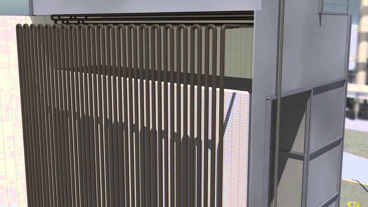
Quest Integrity Group’s furnace tube inspection system, FTIS™, detects and measures damage mechanisms and deformations in the convection and radiant coils of process fired heaters.
furnace radiant and convection section 주제에 대한 자세한 내용은 여기를 참조하세요.
Industrial furnace – Wikipedia
Convection section. The convection section is located above the radiant section where it is cooler to recover additional heat.
Source: en.wikipedia.org
Date Published: 8/21/2022
View: 2597
API 560 Fired Heater Design – Convection Section – HeaterSIM
The main purpose of the convection section is to absorb energy from the hot flue gas leaving the radiant section. The convection Section usually consists of …
Source: www.heatersim.com
Date Published: 1/27/2021
View: 3817
Furnace – New World Encyclopedia
The convection section is located above the radiant section, where it is cooler to recover additional heat. In this section …
Source: www.newworldencyclopedia.org
Date Published: 10/18/2022
View: 218
Simulation of heat transfer in the convection section of fired …
Heat is transferred in a fired heater by both convection and radiation in both sections of the furnace, where radiation is the dominant type of heat transfer in …
Source: pp.bme.hu
Date Published: 11/26/2022
View: 9503
Fired Heaters – TechEngineering
The heater with radiant and convection section can reach higher power and allow higher efficiency. The convection section, which has horizontal axis, …
Source: www.techengineering.it
Date Published: 4/5/2021
View: 9632
Fired Heaters: Working, Components, Types, Function …
The portion of the heater in which the heat is transferred to tubes primarily by convection. Brge wall: The section separates the radiant & convection section …
Source: whatispiping.com
Date Published: 12/14/2021
View: 5658
FURNACES – Thermopedia
Furnaces employing combustion produce a hot gas which transfers heat to the material by radiation and convection. Sols are heated by direct contact, …
Source: www.thermopedia.com
Date Published: 8/18/2021
View: 3273
Unit 3. Furnaces
In a fired furnace, radiant heat is emitted from the combustion of … convection section because most of the heat it receives is by convection.
Source: portal.tpu.ru:7777
Date Published: 8/13/2021
View: 7007
주제와 관련된 이미지 furnace radiant and convection section
주제와 관련된 더 많은 사진을 참조하십시오 Furnace Tube Inspection System – FTIS™. 댓글에서 더 많은 관련 이미지를 보거나 필요한 경우 더 많은 관련 기사를 볼 수 있습니다.
주제에 대한 기사 평가 furnace radiant and convection section
- Author: QuestIntegrityGrp
- Views: 조회수 23,961회
- Likes: 좋아요 181개
- Date Published: 2015. 7. 22.
- Video Url link: https://www.youtube.com/watch?v=flUKuiD-Uso
What is convection section in furnace?
The convection section is located above the radiant section where it is cooler to recover additional heat. Heat transfer takes place by convection here, and the tubes are finned to increase heat transfer.
Which section of furnace tubes is heated by both radiation and convection?
The flames heat the tubes, which in turn heat the fluid inside in the first part of the furnace known as the radiant section or firebox. In this chamber, where combustion takes place, the heat is transferred mainly by radiation to tubes around the fire in the chamber.
Does a furnace use convection or radiation?
Furnaces employing combustion produce a hot gas which transfers heat to the material by radiation and convection. Solids are heated by direct contact, but fluids are usually heated indirectly, being carried inside pipes within the furnace.
What section of a furnace contains the burners?
The section in a furnace that contains the burners and open flames is called the firebox. The firebox is lined with a refractory layer, a brick lining that reflects heat back into the furnace.
What is the meaning of convection section?
[kən′vek·shən ‚sek·shən] (engineering) That portion of the furnace in which tubes receive heat from the flue gases by convection.
Where are the radiant tubes located in a furnace?
6. Where are the radiant tubes located in a furnace? Radiant tubes, or coils, are located along the walls of the firebox.
What is the principle of furnace?
Whatever fuel a furnace uses, it operates on the principle of forced air heating. The furnace transfers heat to air, which blower fans then send through the ductwork of a house and out vents.
What is furnace and its types?
There are four main types of furnaces: natural gas, oil, electric, and propane. Electric furnaces can heat the air by exposing heated elements, while other types of furnaces typically require a heat exchanger or chamber that warms the surrounding air.
What is heat duty of furnace?
9.1 Overview. Process heat duty is the heat required to be added or be removed from the process fluids to create the required change in temperature. It can be in the form of sensible heat, latent heat, or latent heat of vaporization.
What is radiant and convection?
Radiant heat warms objects and surfaces without heating the air in between. Those objects warm up directly and radiate back. Convection warms the air, which is a triple inefficiency. The air has to: Warm up.
How conduction is important in furnace?
In a fuel-fired heating process, heat enters the charge through its surface (by radiation or by convection) and diffuses throughout the charge by conduction. This heat flow requires a difference in temperature within the charge. Steady heat flows through a flat furnace charge.
How does a radiant heat system work?
Radiant floor heating systems produce heat through thermal radiation. By heating the floor rather than the surrounding air, they provide indirect, diffused heat that radiates from the floor up. This heat is absorbed by surrounding objects, and they in turn help to warm the entire room.
What are the different parts of a furnace?
- Pilot light. …
- Thermocouple. …
- Hot surface ignitor. …
- Flame sensor. …
- Gas valve. …
- Burners. …
- Heat exchanger. …
- Draft inducer motor.
What is the top part of a furnace called?
This photo shows you how the furnace is divided into two cabinets: the burner cabinet (top) and the blower cabinet (bottom).
What is heat exchanger in furnace?
The heat exchanger is the part of your furnace that heats your home’s air. It is made of metal coils that are designed to absorb and transfer heat. Here’s how the heating process works in your furnace: The burners in your furnace heat the coils of the heat exchanger.
Is convection forced air?
Natural and Forced: Two Forms of Convection
When the medium transferring the heat is moving by itself, that is called forced convection. An example would be when air is forced by a fan.
What is conduction in HVAC?
A heat exchanger in an HVAC system uses conduction to transfer heat. This is the traveling of heat energy from one molecule to another using direct contact with the temperature source. HVAC heat exchangers will either heat or cool the air with conduction, but they need the proper medium from which to get the energy.
Which heating equipment uses steam or hot water in providing heat to an interior space through intermediary fluid movement?
Household Furnaces. A household furnace is a major appliance that is permanently installed to provide heat to an interior space through intermediary fluid movement, which may be air, steam, or hot water.
Industrial furnace
Device used for providing heat in industrial applications
An industrial chamber furnace, used to heat steel billets for open-die forging
An industrial furnace, also known as a direct heater or a direct fired heater, is a device used to provide heat for an industrial process, typically higher than 400 degrees Celsius.[1] They are used to provide heat for a process or can serve as reactor which provides heats of reaction. Furnace designs vary as to its function, heating duty, type of fuel and method of introducing combustion air. Heat is generated by an industrial furnace by mixing fuel with air or oxygen, or from electrical energy. The residual heat will exit the furnace as flue gas.[1] These are designed as per international codes and standards the most common of which are ISO 13705 (Petroleum and natural gas industries — Fired heaters for general refinery service) / American Petroleum Institute (API) Standard 560 (Fired Heater for General Refinery Service). Types of industrial furnaces include batch ovens, vacuum furnaces, and solar furnaces. Industrial furnaces are used in applications such as chemical reactions, cremation, oil refining, and glasswork.
Overview [ edit ]
Schematic diagram of an industrial process furnace
Fuel flows into the burner and is burnt with air provided from an air blower. There can be more than one burner in a particular furnace which can be arranged in cells which heat a particular set of tubes. Burners can also be floor mounted, wall mounted or roof mounted depending on design. The flames heat up the tubes, which in turn heat the fluid inside in the first part of the furnace known as the radiant section or firebox. In this chamber where combustion takes place, the heat is transferred mainly by radiation to tubes around the fire in the chamber.
The fluid to be heated passes through the tubes and is thus heated to the desired temperature. The gases from the combustion are known as flue gas. After the flue gas leaves the firebox, most furnace designs include a convection section where more heat is recovered before venting to the atmosphere through the flue gas stack. (HTF=Heat Transfer Fluid. Industries also use their furnaces to heat a secondary fluid with special additives like anti-rust and high heat transfer efficiency. This heated fluid is then circulated round the whole plant to heat exchangers to be used wherever heat is needed instead of directly heating the product line as the product or material may be volatile or prone to cracking at the furnace temperature.)
Components [ edit ]
Radiant section [ edit ]
Middle of radiant section
The radiant section is where the tubes receive almost all its heat by radiation from the flame. In a vertical, cylindrical furnace, the tubes are vertical. Tubes can be vertical or horizontal, placed along the refractory wall, in the middle, etc., or arranged in cells. Studs are used to hold the insulation together and on the wall of the furnace. They are placed about 1 ft (300 mm) apart in this picture of the inside of a furnace.
The tubes, shown below, which are reddish brown from corrosion, are carbon steel tubes and run the height of the radiant section. The tubes are a distance away from the insulation so radiation can be reflected to the back of the tubes to maintain a uniform tube wall temperature. Tube guides at the top, middle and bottom hold the tubes in place.
Convection section [ edit ]
Convection section
The convection section is located above the radiant section where it is cooler to recover additional heat. Heat transfer takes place by convection here, and the tubes are finned to increase heat transfer. The first three tube rows in the bottom of the convection section and at the top of the radiant section is an area of bare tubes (without fins) and are known as the shield section (“shock tubes”), so named because they are still exposed to plenty of radiation from the firebox and they also act to shield the convection section tubes, which are normally of less resistant material from the high temperatures in the firebox.
The area of the radiant section just before flue gas enters the shield section and into the convection section called the bridgezone. A crossover is the tube that connects from the convection section outlet to the radiant section inlet. The crossover piping is normally located outside so that the temperature can be monitored and the efficiency of the convection section can be calculated. The sightglass at the top allows personnel to see the flame shape and pattern from above and visually inspect if flame impingement is occurring. Flame impingement happens when the flame touches the tubes and causes small isolated spots of very high temperature.
Radiant coil [ edit ]
This is a series of tubes horizontal/ vertical hairpin type connected at ends (with 180° bends) or helical in construction. The radiant coil absorbs heat through radiation. They can be single pass or multi pass depending upon the process-side pressure drop allowed. The radiant coils and bends are housed in the radiant box. Radiant coil materials vary from carbon steel for low temperature services to high alloy steels for high temperature services. These are supported from the radiant side walls or hanging from the radiant roof. Material of these supports is generally high alloy steel. While designing the radiant coil, care is taken so that provision for expansion (in hot conditions) is kept.
Burner [ edit ]
Furnace burner
The burner in the vertical, cylindrical furnace as above, is located in the floor and fires upward. Some furnaces have side fired burners, such as in train locomotives. The burner tile is made of high temperature refractory and is where the flame is contained. Air registers located below the burner and at the outlet of the air blower are devices with movable flaps or vanes that control the shape and pattern of the flame, whether it spreads out or even swirls around. Flames should not spread out too much, as this will cause flame impingement. Air registers can be classified as primary, secondary and if applicable, tertiary, depending on when their air is introduced.
The primary air register supplies primary air, which is the first to be introduced in the burner. Secondary air is added to supplement primary air. Burners may include a pre-mixer to mix the air and fuel for better combustion before introducing into the burner. Some burners even use steam as premix to preheat the air and create better mixing of the fuel and heated air. The floor of the furnace is mostly made of a different material from that of the wall, typically hard castable refractory to allow technicians to walk on its floor during maintenance.
A furnace can be lit by a small pilot flame or in some older models, by hand. Most pilot flames nowadays are lit by an ignition transformer (much like a car’s spark plugs). The pilot flame in turn lights up the main flame. The pilot flame uses natural gas while the main flame can use both diesel and natural gas. When using liquid fuels, an atomizer is used, otherwise, the liquid fuel will simply pour onto the furnace floor and become a hazard. Using a pilot flame for lighting the furnace increases safety and ease compared to using a manual ignition method (like a match).
Sootblower [ edit ]
Sootblowers are found in the convection section. As this section is above the radiant section and air movement is slower because of the fins, soot tends to accumulate here. Sootblowing is normally done when the efficiency of the convection section is decreased. This can be calculated by looking at the temperature change from the crossover piping and at the convection section exit.
Sootblowers utilize flowing media such as water, air or steam to remove deposits from the tubes. This is typically done during maintenance with the air blower turned on. There are several different types of sootblowers used. Wall blowers of the rotary type are mounted on furnace walls protruding between the convection tubes. The lances are connected to a steam source with holes drilled into it at intervals along its length. When it is turned on, it rotates and blows the soot off the tubes and out through the stack.
Stack [ edit ]
Stack damper
The flue gas stack is a cylindrical structure at the top of all the heat transfer chambers. The breeching directly below it collects the flue gas and brings it up high into the atmosphere where it will not endanger personnel.
The stack damper contained within works like a butterfly valve and regulates draft (pressure difference between air intake and air exit) in the furnace, which is what pulls the flue gas through the convection section. The stack damper also regulates the heat lost through the stack. As the damper closes, the amount of heat escaping the furnace through the stack decreases, but the pressure or draft in the furnace increases which poses risks to those working around it if there are air leakages in the furnace, the flames can then escape out of the firebox or even explode if the pressure is too great.
Insulation [ edit ]
Insulation is an important part of the furnace because it improves efficiency by minimizing heat escape from the heated chamber. Refractory materials such as firebrick, castable refractories and ceramic fibre, are used for insulation. The floor of the furnace are normally castable type refractories while those on the walls are nailed or glued in place. Ceramic fibre is commonly used for the roof and wall of the furnace and is graded by its density and then its maximum temperature rating. For example, 8# 2,300 °F means 8 lb/ft3 density with a maximum temperature rating of 2,300 °F. The actual service temperature rating for ceramic fiber is a bit lower than the maximum rated temperature. (i.e. 2300 °F is only good to 2145 °F before permanent linear shrinkage).
Foundations [ edit ]
Concrete pillars are foundation on which the heater is mounted. They can be four nos. for smaller heaters and may be up to 24 nos. for large size heaters. Design of pillars and entire foundation is done based on the load bearing capacity of soil and seismic conditions prevailing in the area. Foundation bolts are grouted in foundation after installation of the heater.
Access doors [ edit ]
The heater body is provided with access doors at various locations. Access doors are to be used only during shutdown of heater. The normal size of the access door is 600×400 mm, which is sufficient for movement of people/ material into and out of the heater. During operation the access doors are properly bolted using leak proof high temperature gaskets.
See also [ edit ]
References [ edit ]
New World Encyclopedia
Tiangong Kaiwu Illustrations of Chinese silversmiths smelting silver ore and separating lead from it. Taken from encyclopedia (1637), by Song Yingxing (1587-1666).
A furnace (from the Latin word fornax, meaning “oven”) is an appliance that produces heat. The heat in a furnace is usually produced by combustion of a fuel such as oil, wood, or natural gas. The heat may also be generated by electricity, as in an electric arc furnace, or by induction heating in an induction furnace.
In American English, the term furnace generally refers to the central heater in a home or office, or the heater for an industrial process, and sometimes it is a synonym for kiln, a device used in the production of ceramics. In British English, the term furnace almost exclusively means an industrial furnace, whereas a household heater is called a boiler or heater. Industrial furnaces are used for many applications, such as the extraction of metals from ores (smelting), the running of chemical reactions, or the refining of oil by fractional distillation.
Household Furnaces
A household furnace is a major appliance that is permanently installed to provide heat to an interior space through intermediary fluid movement, which may be air, steam, or hot water. The most common fuel source for modern furnaces in the United States is natural gas; other common fuel sources include LPG (liquefied petroleum gas), fuel oil, coal or wood. In some cases electrical resistance heating is used as the source of heat, especially where the cost of electricity is low.
Combustion furnaces always need to be vented to the outside. Traditionally, this was through a chimney, which tends to expel heat along with the exhaust. Modern high-efficiency furnaces can be 98 percent efficient and operate without a chimney.[1] The small amount of waste gas and heat are mechanically ventilated through a small tube through the side or roof of the house.
Modern household furnaces are classified as condensing or non-condensing, based on their efficiency in extracting heat from exhaust gases. Furnaces with efficiencies greater than approximately 89 percent extract so much heat from the exhaust that water vapor in the exhaust condenses; they are referred to as condensing furnaces. Such furnaces must be designed to avoid the corrosion that this highly acidic condensate might cause and may need to include a condensate pump to remove the accumulated water. Condensing furnaces can typically deliver savings of 20-35 percent in heating costs, if the old furnace was in the 60 percent Annual Fuel Utilization Efficiency (AFUE) range.
Heat Distribution
The furnace transfers heat to the living space of the building through an intermediary distribution system. If the distribution is through hot water (or other fluid) or through steam, then the furnace is more commonly termed a boiler. One advantage of a boiler is that the furnace can provide hot water for bathing and washing dishes, rather than requiring a separate water heater. A disadvantage, however, is that when the boiler breaks down, it results in loss of both heat and hot water.
A condensing furnace
Air convection heating systems have been in use for over a century, but the older systems relied on a passive air circulation system, in which the higher density of cooler air caused it to sink into the furnace, and the lower density of warmer air caused it to rise in the ductwork. The two forces acted together to drive air circulation in a system, known as “gravity-feed.” The layout of the ducts and furnace was optimized for short, large ducts and the furnace was therefore referred to as an “octopus” furnace.
By comparison, most modern “warm air” furnaces typically use a fan to circulate air into the rooms of house and pull cooler air back to the furnace for reheating. This is called forced-air heat. Because the fan easily overcomes the resistance of the ductwork, the arrangement of ducts can be far more flexible than the octopus of old. In American practice, separate ducts collect cool air to be returned to the furnace. At the furnace, cool air passes into the furnace, usually through an air filter, through the blower, then through the heat exchanger of the furnace, from where it is blown throughout the building. One major advantage of this type of system is that it also enables easy installation of central air conditioning by simply adding a cooling coil at the exhaust of the furnace.
Air is circulated through ductwork, which may be made of sheet metal or plastic “flex” duct and insulated or uninsulated. Unless the ducts and plenums have been sealed using mastic or foil duct tape, the ductwork is likely to have a high leakage of conditioned air, possibly into unconditioned spaces. Another cause of wasted energy is the installation of ductwork in unheated areas, such as attics and crawl spaces; or ductwork of air conditioning systems in attics in warm climates.
The following rare but difficult-to-diagnose failure can occur. If the temperature inside the furnace exceeds a maximum threshold, a safety mechanism with a thermostat will shut the furnace down. A symptom of this failure is that the furnace repeatedly shuts down before the house reaches the desired temperature; this is commonly referred to as the furnace “riding the high limit switch.” This condition commonly occurs if the temperature setting of the high limit thermostat is set too close to the normal operating temperature of the furnace. Another situation may occur if a humidifier is incorrectly installed on the furnace and the duct that directs a portion of the humidified air back into the furnace is too large. The solution is to reduce the diameter of the cross-feed tube, or to install a baffle that reduces the volume of re-fed air.
Industrial process furnaces
An industrial furnace, or direct-fired heater, is an equipment that provides heat for a process or chemical reaction. Furnace designs vary as to their function, heating duty, type of fuel, and method of introducing combustion air. However, most process furnaces have some common features.
Fuel flows into the burner and is burnt with air provided from an air blower. A given furnace may have more than one burner, arranged in cells that heat a set of tubes. Burners can be floor-mounted, wall-mounted, or roof-mounted, depending on design. The flames heat the tubes, which in turn heat the fluid inside in the first part of the furnace known as the radiant section or firebox. In this chamber, where combustion takes place, the heat is transferred mainly by radiation to tubes around the fire in the chamber. The heating fluid passes through the tubes and is thus heated to the desired temperature.
The gases from the combustion are known as flue gas. After the flue gas leaves the firebox, most furnace designs include a convection section where more heat is recovered before venting to the atmosphere through the flue gas stack.
In industrial furnaces, a common approach is to heat a secondary fluid called a heat transfer fluid (HTF) that has high heat-transfer efficiency and may contain special additives (such as an anti-rust agent). This heated fluid is then circulated around the whole plant to heat exchangers to be used wherever heat is needed, instead of directly heating the product line, as the product or material may be volatile or prone to cracking at the furnace temperature.
Radiant section
The radiant section is where the tubes receive almost all their heat by radiation from the flame. In a vertical, cylindrical furnace, the tubes are vertical. Tubes can be vertical or horizontal, placed along the refractory wall or around the middle, or arranged in cells. Studs are used to hold the insulation together and on the wall of the furnace. They are placed about one foot (300 mm) apart in the following picture of the inside of a furnace. The tubes, which are reddish brown from corrosion, are carbon steel tubes and run the height of the radiant section. The tubes are a distance away from the insulation so that radiation can be reflected to the back of the tubes to maintain a uniform tube wall temperature. Tube guides at the top, middle, and bottom hold the tubes in place.
Convection section
The convection section is located above the radiant section, where it is cooler to recover additional heat. In this section, heat transfer takes place by convection, and the tubes are finned to increase heat transfer. The first two tube rows at the bottom of the convection section and the top of the radiant section form an area of bare tubes (without fins) and are known as the “shield section,” because they are exposed to plenty of radiation from the firebox and they also shield the convection section tubes, which are normally of less resistant material from the high temperatures in the firebox.
The area of the radiant section just before the flue gas enters the shield section and then the convection section is called the “bridge zone.” The term “crossover” is used to describe the tube that connects from the convection section outlet to the radiant section inlet. The crossover piping is normally located outside, so that the temperature can be monitored and the efficiency of the convection section can be calculated. The sightglass at the top allows personnel to observe the flame shape and pattern from above and to check for “flame impingement”—that is, whether the flame is touching the tubes, causing small, isolated spots of very high temperature.
Burner
The burner in a vertical, cylindrical furnace is generally located in the floor and fires upward. Some furnaces have side-fired burners, as in train locomotives. The burner tile is made of high-temperature refractory material that contains the flame. Air registers located below the burner and at the outlet of the air blower are devices with movable flaps or vanes that control the shape and pattern of the flame, whether it spreads out or swirls around. Flames should not spread out too much, as this will cause flame impingement.
Air registers can be classified as primary, secondary, and (if applicable) tertiary, depending on when the air is introduced. The primary air register supplies primary air, which is the first batch of air to be introduced in the burner. Secondary air is added to supplement primary air. Burners may include a premixer to mix the air and fuel for better combustion before introducing it into the burner. Some burners even use steam in the premix, to preheat the air and create better mixing of the fuel and heated air. The furnace floor is mostly made of a different material from that of the wall, typically hard castable refractory that allows technicians to walk on its floor during maintenance.
A furnace can be lit by a small pilot flame or (in some older models) matches. Most pilot flames nowadays are lit by an ignition transformer (much like a car’s spark plugs). The pilot flame in turn lights up the main flame. The pilot flame uses natural gas, while the main flame may use both diesel and natural gas. For liquid fuels, the fuel is passed through an atomizer, to prevent the liquid fuel from pouring onto the furnace floor and becoming a hazard. Using a pilot flame for lighting the furnace increases safety and ease (compared to using a match).
Sootblower
Sootblowers are found in the convection section. As this section is above the radiant section and air movement is slowed by the fins, soot tends to accumulate here. Sootblowing is normally done when the efficiency of the convection section is decreased. This can be calculated by looking at the temperature change from the crossover piping and at the convection section exit.
Sootblowers utilize flowing media such as water, air, or steam to remove deposits from the tubes. This is typically done during maintenance, with the air blower turned on. Several different types of sootblowers are available. Wall blowers of the rotary type are mounted on furnace walls protruding between the convection tubes. The lances are connected to a steam source with holes drilled into it at intervals along its length. When it is turned on, it rotates and blows the soot off the tubes and out through the stack.
Stack
The flue gas stack is a cylindrical structure at the top of the heat transfer chamber. The breeching directly below it collects the flue gas and releases it high in the atmosphere where it will not endanger personnel.
The stack contains a damper that works like a butterfly valve and regulates the draft (pressure difference between air intake and air outflow) in the furnace. The draft pulls the flue gas through the convection section. The stack damper also regulates the heat lost through the stack. As the damper closes, the amount of heat escaping the furnace through the stack decreases, but the pressure or draft in the furnace increases. This pressure increase poses risks to those working around the furnace if there are air leakages in the furnace, because the flames may then escape out of the firebox or even explode if the pressure is too high.
Insulation
Insulation is an important part of the furnace because it prevents excessive heat loss. Refractory materials such as firebrick, castable refractories, and ceramic fiber are used for insulation. The floors of the furnace are normally castable type refractories, while the refractories on the walls are nailed or glued in place. Ceramic fiber is commonly used for the roof and wall of the furnace and is graded by its density and then its maximum temperature rating. For example, a grade of “8# 2,300°F” means the material has a density of eight lb/ft3 and a maximum temperature rating of 2,300°F. An example of a material with castable composition is kastolite.
Metallurgical furnaces
In metallurgy, several specialized furnaces are used, a number of which are listed below.
Furnaces used in smelters: The blast furnace, used to reduce iron ore to pig iron Steelmaking furnaces, including: Puddling furnace Reverberatory furnace Bessemer converter Open hearth furnace Basic oxygen furnace Electric arc furnace Electric induction furnace
Furnaces used to remelt metal in foundries.
Furnaces used to reheat and heat treat metal for use in: Rolling mills, including tinplate works and slitting mills. Forges.
Vacuum furnaces to heat metals and other materials to very high temperatures, in the presence of a vacuum that reduces potential sources of contamination.
Outdoor wood-fired boilers
Description
An outdoor wood-fired boiler (OWB), also known as a waterstove, wood boiler, or outdoor wood furnace, is a heating technology that has grown in popularity in the northern United States. In most cases, an OWB looks like a small shack with metal siding. It is self-contained, connected to the building it heats through underground insulated water pipes. It contains a metal combustion chamber for a wood fire, surrounded by a water tank or water jacket. The fire heats the water, which is then circulated through the insulated water pipes into the building that is being heated. Once the hot water from the boiler reaches the building, the heat can be transferred to most existing heating systems and the building’s hot water supply.
A damper and fan on the boiler interacts with a thermostat in the building. If the building’s temperature falls, the thermostat triggers the damper to open, allowing more oxygen to enter the combustion chamber. As a result, the fire burns more intensely and raises the water temperature, thereby increasing the heat supplied to the building.
Benefits
OWBs offer several benefits that have increased their popularity. Their large combustion chamber accommodates more fuel than many other forms of wood heat, decreasing the number of times an owner has to add fuel to the fire. Home insurance may cost more for people who heat with an indoor form of wood heat than with an OWB.[2] Moreover, for people with a large supply of free wood and willing to invest the time to prepare the wood and stock the OWB, an OWB can be less expensive than heating with gas, oil, or electricity.
Controversy
OWBs are not without controversy, as their emissions sometimes bother neighbors. Some states and municipalities have banned the devices.[3] They are not currently regulated by the United States Environmental Protection Agency (EPA), unlike other forms of wood heat.[4] Recently, however, the EPA has worked with manufacturers to develop a method for them to identify OWBs that meet a voluntary emissions standard.[5] Some studies conducted on OWBs suggest that they may produce more emissions, most notably particulate matter under 2.5 micrometers (PM 2.5), compared with other heating technologies, but manufacturers dispute these assessments.[6] Exposure to elevated levels of PM 2.5 has been associated with cardiopulmonary health effects and premature death.[7]
As of July 2006, the Hearth, Patio and Barbecue Association (HPBA) and many of the major OWB manufacturers have requested users of their products to follow the “Outdoor Wood Furnace Best Burn Practices.”[8] These guidelines have been set up by the HPBA to help cut down on problems associated with OWBs.
Early in January 2007, the United States Environmental Protection Agency (EPA) initiated a voluntary program for manufacturers of outdoor wood furnaces.[5] The EPA’s primary intent is to encourage manufacturers to produce cleaner models known as Outdoor Wood-fired Hydronic Heaters (OWHH). The EPA also wants those who buy an OWHH/OWB to buy the cleanest models available, which are those that meet EPA performance verified levels. To participate in this program, manufacturers are developing cleaner models, with the goal of distributing these units starting in April 2007.[9]
The EPA now publishes a list of all OWHH/OWB units that pass the new voluntary program.[10] These furnaces come with the ‘orange EPA OWHH tag’ to notify the customer of the unit’s particular emission level output.
See also
Boiler
Cremation
Geothermal system
Humidifier
HVAC
Oven
Solar power
Thermodynamics
Notes
References ISBN links support NWE through referral fees
Davies, Clive. 1970. Calculations in Furnace Technology , 1st ed. Oxford, UK: Pergamon Press. ISBN 0080133665
, 1st ed. Oxford, UK: Pergamon Press. ISBN 0080133665 Dukelow, Samuel G. 1985. Improving Boiler Efficiency , 2nd ed. Research Triangle Park, NC: Instrument Society of America. ISBN 0876648529
, 2nd ed. Research Triangle Park, NC: Instrument Society of America. ISBN 0876648529 Fiveland, W.A., A.L. Crosbie, A.M. Smith, and T.F. Smith (eds.). 1991. Fundamentals of Radiation Heat Transfer . New York: American Society of Mechanical Engineers. ISBN 0791807290
. New York: American Society of Mechanical Engineers. ISBN 0791807290 Goldstick, R., and A. Thumann. 1986. Principles of Waste Heat Recovery . Atlanta, GA: Fairmont Press. ISBN 0881730157
. Atlanta, GA: Fairmont Press. ISBN 0881730157 Gray, W.A., and R. Muller. 1974. Engineering Calculations in Radiative Heat Transfer , 1st ed. Oxford, UK: Pergamon Press Ltd. ISBN 0080177875
, 1st ed. Oxford, UK: Pergamon Press Ltd. ISBN 0080177875 Lieberman, P., and E.T. Lieberman. 2003. Working Guide to Process Equipment , 2nd ed. New York: McGraw-Hill. ISBN 0071390871
, 2nd ed. New York: McGraw-Hill. ISBN 0071390871 Perry, R.H., and D.W. Green (eds.). 1997. Perry’s Chemical Engineers’ Handbook , 7th ed. New York: McGraw-Hill. ISBN 0070498415
, 7th ed. New York: McGraw-Hill. ISBN 0070498415 Warring, R.H. 1982. Handbook of Valves, Piping and Pipelines . Houston, TX: Gulf Publishing Company. ISBN 0872018857
. Houston, TX: Gulf Publishing Company. ISBN 0872018857 Whitehouse, R.C. (ed.). 1993. The Valve and Actuator User’s Manual. London, UK: Mechanical Engineering Publications. ISBN 0852988052
FURNACES
Introduction A furnace is a device in which heat is generated and transferred to materials with the object of bringing about physical and chemical changes. The source of heat is usually combustion of solid, liquid or gaseous fuel, or electrical energy applied through resistance heating (Joule heating) or inductive heating. However, solar energy can provide a clean source of high temperature if focused onto a small area. This was recognized over two hundred years ago by Lavoisier who built a large mobile “magnifying glass” system, Figure 1, to bring about the combustion of metals in a sealed glass container and subsequently the demise of the phlogiston theory. Figure 1. Lavoisier’s solar powered furnace c 1774. Furnaces employing combustion produce a hot gas which transfers heat to the material by radiation and convection. Solids are heated by direct contact, but fluids are usually heated indirectly, being carried inside pipes within the furnace. Alternatively, a Regenerative Heat Exchanger may be used to transfer heat from the combustion gases. Indirect heating has the advantage of avoiding contamination by combustion products. There are two principle categories of indirect heating furnace. The first is that of Boilers, where the heat is used to generate steam for power generation or process plant use. The second is that of furnaces designed to heat process fluids other than water. Some of the latter category are conventional heaters used simply to increase the fluid temperature, others are process heaters used to bring about physical and chemical changes in the products, for example distillation, and pyrolysis of hydrocarbons or catalytic steam-gas reforming of synthetic natural gas.
Process Heaters In the petrochemical industry process furnaces, or process heaters, are usually fired by oil or gas. They are designed to ensure that the fluid receives the right amount of heat and has the required residence time within specified temperature limits. This is achieved by appropriate disposition of tubes and careful control of firing rate and fluid flow. The following Figure 2 shows three typical geometries. Figure 2. Process heaters. (From the Heat Exchanger Design Handbook, Hemisphere Publications. With permission.)
Furnace Fuels The following tables give the properties of gaseous, liquid and solid fuels used in furnaces. Gross calorific value includes the heat released by the condensation and cooling of combustion products, and the combustion air/fuel ratio is the stoichiometric value based on theoretically perfect combustion (see Combustion). In practice, excess air is required to ensure complete combustion. The excess is usually about 10% of the stoichiometric value for premixed gaseous fuels, 20% for distillate oil and pulverized coal, and 30% for residual oil, although lower values may be achieved with efficient burners. Table 1. Properties of selected gaseous fuelsa (aFrom the Heat Exchanger Design Handbook , Hemisphere Publications. With permission.)
Furnace Heat Balance The rate of heat released in a fuel fired furnace is given by the product of the mass rate of feed of fuel, , and the calorific value Δh f , i.e., (1) The heat generated by combustion appears initially as sensible heat in the gaseous products of combustion, generated at the rate . If this were an adiabatic process (i.e., no heat transfer), the gas would attain the adiabatic flame temperature, T f , given by (2) where T 0 is the inlet air/fuel temperature and c pg an appropriate averaged specific heat capacity of the gases for the range T 0 to T f . However, as illustrated in Figure 3, part of the heat generated passes to the tubes containing the process fluid at rate and part is lost through the furnace walls at rate . The remainder escapes at rate as waste heat of the combustion products leaving the furnace. The overall heat balance therefore is (3) Because of this the actual gas temperature, T g , reached in the furnace is less than the adiabatic flame temperature, T f . Neglecting wall losses an approximate value of T g can be obtained from (4) For example, in a typical oil fired furnace the value of T f is 2,200 K and the value of T g is 1,300 K [Shires, Hewitt and Bott (1994)]. Table 2. Properties of selected liquid and solid fuelsa (aFrom the Heat Exchanger Design Handbook , Hemisphere Publications. With permission.) Figure 3. Furnace heat balances. The rate of heat transfer, , from the hot gases to the tubes is a function of the gas temperature as well as the radiation properties of the gases, the geometry of the furnace and tubes, and the emissivity of the tube surface. In applying simple furnace models iteration is therefore necessary.
Furnace Radiation In most process heaters, the major part of the heat transfer from the hot gases to the tubes is by radiation. To calculate the radiative component it is necessary to know the effective emissivity, ε g , of the combustion gases (typical value 0.25). This is dependent on the ratio of the partial pressures of CO 2 and H 2 , the temperatures of the gas and the radiation source and the effective size of the radiating gas cloud. The latter is represented by the term pLo, the product of partial pressure and effective length of the furnace—a term first introduced by H. C. Hottel. For details of the procedure see Hottel and Sarofim (1967) and Hewitt, Shires and Bott (1994). The rate of heat transfer to the furnace product is also a function of the geometry of the tube banks and the fraction of the furnace surface area covered by them. If the effective area of the tubes, A 1 , is only a small fraction of the total area. A t , (Figure 4a), the surface receives blackbody radiation (see Radiative Heat Transfer) and the rate of heat transfer is independent of gas emissivity, ε g , i.e., (5) where ε 1 is the effective emissivity of the receiving surface and T 1 its temperature and σ is the Stefan-Boltzmann constant, 5.670 × 10⁻⁸ W/m2K4. On the other hand, if A 1 is almost equal to the total surface area, A t , then (6) Intermediate ratios are covered by the speckled surface equation [Hottel and Sarofim (1967)]. (7) where C = A 1 /A t . Figure 4. Effect of heat sink area on effective emissivity. (a) Small heat sink area; (b) large heat sink area; (e) example based on Eq. (7) with ε g = 0.3 and ε 1 = 0.85.
Effects of Tube Bank Geometry In practice the area, A 1 , receiving radiation is a tube bank, Figure 5, which intercepts only a fraction of the incident radiation; some passes through to the refractory wall and is re-irradiated. For a detailed analysis see Hottel and Sarofim (1967). Figure 5. Plane surface equivalent of tube bank heat sink; B = p/d. The fraction of radiation intercepted by a single row of tubes having a pitch to diameter ratio B (equals p/d) is given by (8) Figure 6 shows F as a function of B for one and two rows of tubes. Figure 6. Fraction of incident radiation intercepted by tubes. (From the Heat Exchanger Design Handbook, Hemisphere Publications. With permission.) The effective emissivity based on the projected area using Eq. (7) and allowing for re-irradiation from the refractory backing is (9) This is illustrated in Figure 7 for a typical tube surface emissivity of 0.85. Figure 7. Effective emissivity of equivalent plane surface. The relationship between the rate of heat transfer, , from the gas to the tubes and the gas temperature, T g , is obtained by combining Eqs. (6), (7) and (8). This in turn can be combined with Eq. (3) to determine the furnace thermal characteristics. An example of this procedure is described in Hewitt, Shires and Bolt (1994).
Furnace Models The complete mathematical description of a practical furnace is complex, combining aerodynamics, chemical reactions and heat transfer, and computer programs are normally used for detailed solutions. There are two basic types of approach; zone methods and flux methods. Zone methods are employed when the heat release pattern from the flame is known or can be calculated independently. Conceptually, the furnace and its walls are divided into discrete zones, the effective exchange areas between zones are determined, and radiative heat transfer corresponding to the prescribed heat release pattern is calculated. In flux methods, instead of dividing the space into zones the radiation arriving at a point in the system is itself divided into a number of characteristic directions, representing averages over a specified solid angle. Flux methods are well suited for use in combination with modern methods of prediction of fluid flow and mixing. Simultaneous solutions of the radiative heat transfer equations using flux methods and turbulent flow models are feasible. For further information on these two methods see Beer (1974), and Afgan and Beer (1974), where examples of their application can be found.
Industrial furnace
Device used for providing heat in industrial applications
An industrial chamber furnace, used to heat steel billets for open-die forging
An industrial furnace, also known as a direct heater or a direct fired heater, is a device used to provide heat for an industrial process, typically higher than 400 degrees Celsius.[1] They are used to provide heat for a process or can serve as reactor which provides heats of reaction. Furnace designs vary as to its function, heating duty, type of fuel and method of introducing combustion air. Heat is generated by an industrial furnace by mixing fuel with air or oxygen, or from electrical energy. The residual heat will exit the furnace as flue gas.[1] These are designed as per international codes and standards the most common of which are ISO 13705 (Petroleum and natural gas industries — Fired heaters for general refinery service) / American Petroleum Institute (API) Standard 560 (Fired Heater for General Refinery Service). Types of industrial furnaces include batch ovens, vacuum furnaces, and solar furnaces. Industrial furnaces are used in applications such as chemical reactions, cremation, oil refining, and glasswork.
Overview [ edit ]
Schematic diagram of an industrial process furnace
Fuel flows into the burner and is burnt with air provided from an air blower. There can be more than one burner in a particular furnace which can be arranged in cells which heat a particular set of tubes. Burners can also be floor mounted, wall mounted or roof mounted depending on design. The flames heat up the tubes, which in turn heat the fluid inside in the first part of the furnace known as the radiant section or firebox. In this chamber where combustion takes place, the heat is transferred mainly by radiation to tubes around the fire in the chamber.
The fluid to be heated passes through the tubes and is thus heated to the desired temperature. The gases from the combustion are known as flue gas. After the flue gas leaves the firebox, most furnace designs include a convection section where more heat is recovered before venting to the atmosphere through the flue gas stack. (HTF=Heat Transfer Fluid. Industries also use their furnaces to heat a secondary fluid with special additives like anti-rust and high heat transfer efficiency. This heated fluid is then circulated round the whole plant to heat exchangers to be used wherever heat is needed instead of directly heating the product line as the product or material may be volatile or prone to cracking at the furnace temperature.)
Components [ edit ]
Radiant section [ edit ]
Middle of radiant section
The radiant section is where the tubes receive almost all its heat by radiation from the flame. In a vertical, cylindrical furnace, the tubes are vertical. Tubes can be vertical or horizontal, placed along the refractory wall, in the middle, etc., or arranged in cells. Studs are used to hold the insulation together and on the wall of the furnace. They are placed about 1 ft (300 mm) apart in this picture of the inside of a furnace.
The tubes, shown below, which are reddish brown from corrosion, are carbon steel tubes and run the height of the radiant section. The tubes are a distance away from the insulation so radiation can be reflected to the back of the tubes to maintain a uniform tube wall temperature. Tube guides at the top, middle and bottom hold the tubes in place.
Convection section [ edit ]
Convection section
The convection section is located above the radiant section where it is cooler to recover additional heat. Heat transfer takes place by convection here, and the tubes are finned to increase heat transfer. The first three tube rows in the bottom of the convection section and at the top of the radiant section is an area of bare tubes (without fins) and are known as the shield section (“shock tubes”), so named because they are still exposed to plenty of radiation from the firebox and they also act to shield the convection section tubes, which are normally of less resistant material from the high temperatures in the firebox.
The area of the radiant section just before flue gas enters the shield section and into the convection section called the bridgezone. A crossover is the tube that connects from the convection section outlet to the radiant section inlet. The crossover piping is normally located outside so that the temperature can be monitored and the efficiency of the convection section can be calculated. The sightglass at the top allows personnel to see the flame shape and pattern from above and visually inspect if flame impingement is occurring. Flame impingement happens when the flame touches the tubes and causes small isolated spots of very high temperature.
Radiant coil [ edit ]
This is a series of tubes horizontal/ vertical hairpin type connected at ends (with 180° bends) or helical in construction. The radiant coil absorbs heat through radiation. They can be single pass or multi pass depending upon the process-side pressure drop allowed. The radiant coils and bends are housed in the radiant box. Radiant coil materials vary from carbon steel for low temperature services to high alloy steels for high temperature services. These are supported from the radiant side walls or hanging from the radiant roof. Material of these supports is generally high alloy steel. While designing the radiant coil, care is taken so that provision for expansion (in hot conditions) is kept.
Burner [ edit ]
Furnace burner
The burner in the vertical, cylindrical furnace as above, is located in the floor and fires upward. Some furnaces have side fired burners, such as in train locomotives. The burner tile is made of high temperature refractory and is where the flame is contained. Air registers located below the burner and at the outlet of the air blower are devices with movable flaps or vanes that control the shape and pattern of the flame, whether it spreads out or even swirls around. Flames should not spread out too much, as this will cause flame impingement. Air registers can be classified as primary, secondary and if applicable, tertiary, depending on when their air is introduced.
The primary air register supplies primary air, which is the first to be introduced in the burner. Secondary air is added to supplement primary air. Burners may include a pre-mixer to mix the air and fuel for better combustion before introducing into the burner. Some burners even use steam as premix to preheat the air and create better mixing of the fuel and heated air. The floor of the furnace is mostly made of a different material from that of the wall, typically hard castable refractory to allow technicians to walk on its floor during maintenance.
A furnace can be lit by a small pilot flame or in some older models, by hand. Most pilot flames nowadays are lit by an ignition transformer (much like a car’s spark plugs). The pilot flame in turn lights up the main flame. The pilot flame uses natural gas while the main flame can use both diesel and natural gas. When using liquid fuels, an atomizer is used, otherwise, the liquid fuel will simply pour onto the furnace floor and become a hazard. Using a pilot flame for lighting the furnace increases safety and ease compared to using a manual ignition method (like a match).
Sootblower [ edit ]
Sootblowers are found in the convection section. As this section is above the radiant section and air movement is slower because of the fins, soot tends to accumulate here. Sootblowing is normally done when the efficiency of the convection section is decreased. This can be calculated by looking at the temperature change from the crossover piping and at the convection section exit.
Sootblowers utilize flowing media such as water, air or steam to remove deposits from the tubes. This is typically done during maintenance with the air blower turned on. There are several different types of sootblowers used. Wall blowers of the rotary type are mounted on furnace walls protruding between the convection tubes. The lances are connected to a steam source with holes drilled into it at intervals along its length. When it is turned on, it rotates and blows the soot off the tubes and out through the stack.
Stack [ edit ]
Stack damper
The flue gas stack is a cylindrical structure at the top of all the heat transfer chambers. The breeching directly below it collects the flue gas and brings it up high into the atmosphere where it will not endanger personnel.
The stack damper contained within works like a butterfly valve and regulates draft (pressure difference between air intake and air exit) in the furnace, which is what pulls the flue gas through the convection section. The stack damper also regulates the heat lost through the stack. As the damper closes, the amount of heat escaping the furnace through the stack decreases, but the pressure or draft in the furnace increases which poses risks to those working around it if there are air leakages in the furnace, the flames can then escape out of the firebox or even explode if the pressure is too great.
Insulation [ edit ]
Insulation is an important part of the furnace because it improves efficiency by minimizing heat escape from the heated chamber. Refractory materials such as firebrick, castable refractories and ceramic fibre, are used for insulation. The floor of the furnace are normally castable type refractories while those on the walls are nailed or glued in place. Ceramic fibre is commonly used for the roof and wall of the furnace and is graded by its density and then its maximum temperature rating. For example, 8# 2,300 °F means 8 lb/ft3 density with a maximum temperature rating of 2,300 °F. The actual service temperature rating for ceramic fiber is a bit lower than the maximum rated temperature. (i.e. 2300 °F is only good to 2145 °F before permanent linear shrinkage).
Foundations [ edit ]
Concrete pillars are foundation on which the heater is mounted. They can be four nos. for smaller heaters and may be up to 24 nos. for large size heaters. Design of pillars and entire foundation is done based on the load bearing capacity of soil and seismic conditions prevailing in the area. Foundation bolts are grouted in foundation after installation of the heater.
Access doors [ edit ]
The heater body is provided with access doors at various locations. Access doors are to be used only during shutdown of heater. The normal size of the access door is 600×400 mm, which is sufficient for movement of people/ material into and out of the heater. During operation the access doors are properly bolted using leak proof high temperature gaskets.
See also [ edit ]
References [ edit ]
API 560 Fired Heater Design
Convection Section This article is a general introduction into some of the main considerations necessary when designing the Convection Section of a Fired Heater. The detailed heat transfer calculations and correlations are not detailed within this article (for more details on such procedures, please feel free to contact us).
The main purpose of the convection section is to absorb energy from the hot flue gas leaving the radiant section. The convection Section usually consists of bare and finned tube bundles and plays a crucial role in maximising the efficiency of the heater. As the name suggests, the primary mode of heat transfer within this area is ‘Convective’.
Often the lowest 2 or 3 rows are bare tube, whilst the remaining rows are typically finned tubes. The purpose of the fins is to increase the surface area for heat transfer. The heater designer will use a combination of no. of tube rows, the length of the tubes and the extent of finning, in order to adjust the surface area for heat transfer.
There are 3 main type of extended surfaces that are most commonly used in Convection Sections tubes, as shown below:
Convection Section Tube Types
Studs are most commonly used with heaters firing Fuel Oil, since deposits from the flue gas can more easily be cleaned from studded tubes than Serrated or Solid Finned tubes, which are more commonly used for heaters firing gaseous fuels. Sootblower lanes are usually incorporated into the design to allow for tube cleaning (either by manual steam lances or automated retractable systems).
Note: API 560 defines the acceptable dimensions of each of these extended surface types.
Flue Gas Pressure Drop
One of the important areas of consideration is the pressure drop of the flue gas as it flows over the tube bundles. The size of the stack is directly influenced by this factor, since a larger stack will be required to create sufficient draft to overcome these flue losses and maintain -2.5 mm(H2O)g at the arch (as per API 560 requirements).
One way of mitigating the impact on the stack size is to utilise an Induced Draft Fan (ID Fan), which will be designed to pull the flue gas through the tube bundle and any associated ducting.
Appropriate Size for Radiant Section The Convection Section is usually mounted on top of the Radiant Section (although some designs may have ‘off-set’ convection sections). This means that designer will have to carefully select the ‘Number of Rubes Per Row’ AND the ‘Tube Length’ appropriately in order to fit inside the radiant section footprint.
In addition, the heater designer needs to ensure that the No. of Tubes Per Row is suitable for the overall number of process flow passes within the heater.
Additional Process Streams
Flue Gas Pressure Drop The convection section also offers a convenient location for heating additional process streams, such as Steam Generation or Boiler Feed Water (BFW). The tubes with these streams may have a different tube size and ‘No. of Tubes Per Row’ to the main process coils. The additional of such secondary process streams can help to improve the overall efficiency and energy management of the site in general, not just the heater.
Insulation The convection section is usually lined with Castable Refractory, with the hot face usually having the robust/dense layer material. However, in recent years, convection sections are commonly being designed with Ceramic Fibre lining in order to minimise weight and ramp up times during start up (which must be steadily carried out when using Castable refractory).
New World Encyclopedia
Tiangong Kaiwu Illustrations of Chinese silversmiths smelting silver ore and separating lead from it. Taken from encyclopedia (1637), by Song Yingxing (1587-1666).
A furnace (from the Latin word fornax, meaning “oven”) is an appliance that produces heat. The heat in a furnace is usually produced by combustion of a fuel such as oil, wood, or natural gas. The heat may also be generated by electricity, as in an electric arc furnace, or by induction heating in an induction furnace.
In American English, the term furnace generally refers to the central heater in a home or office, or the heater for an industrial process, and sometimes it is a synonym for kiln, a device used in the production of ceramics. In British English, the term furnace almost exclusively means an industrial furnace, whereas a household heater is called a boiler or heater. Industrial furnaces are used for many applications, such as the extraction of metals from ores (smelting), the running of chemical reactions, or the refining of oil by fractional distillation.
Household Furnaces
A household furnace is a major appliance that is permanently installed to provide heat to an interior space through intermediary fluid movement, which may be air, steam, or hot water. The most common fuel source for modern furnaces in the United States is natural gas; other common fuel sources include LPG (liquefied petroleum gas), fuel oil, coal or wood. In some cases electrical resistance heating is used as the source of heat, especially where the cost of electricity is low.
Combustion furnaces always need to be vented to the outside. Traditionally, this was through a chimney, which tends to expel heat along with the exhaust. Modern high-efficiency furnaces can be 98 percent efficient and operate without a chimney.[1] The small amount of waste gas and heat are mechanically ventilated through a small tube through the side or roof of the house.
Modern household furnaces are classified as condensing or non-condensing, based on their efficiency in extracting heat from exhaust gases. Furnaces with efficiencies greater than approximately 89 percent extract so much heat from the exhaust that water vapor in the exhaust condenses; they are referred to as condensing furnaces. Such furnaces must be designed to avoid the corrosion that this highly acidic condensate might cause and may need to include a condensate pump to remove the accumulated water. Condensing furnaces can typically deliver savings of 20-35 percent in heating costs, if the old furnace was in the 60 percent Annual Fuel Utilization Efficiency (AFUE) range.
Heat Distribution
The furnace transfers heat to the living space of the building through an intermediary distribution system. If the distribution is through hot water (or other fluid) or through steam, then the furnace is more commonly termed a boiler. One advantage of a boiler is that the furnace can provide hot water for bathing and washing dishes, rather than requiring a separate water heater. A disadvantage, however, is that when the boiler breaks down, it results in loss of both heat and hot water.
A condensing furnace
Air convection heating systems have been in use for over a century, but the older systems relied on a passive air circulation system, in which the higher density of cooler air caused it to sink into the furnace, and the lower density of warmer air caused it to rise in the ductwork. The two forces acted together to drive air circulation in a system, known as “gravity-feed.” The layout of the ducts and furnace was optimized for short, large ducts and the furnace was therefore referred to as an “octopus” furnace.
By comparison, most modern “warm air” furnaces typically use a fan to circulate air into the rooms of house and pull cooler air back to the furnace for reheating. This is called forced-air heat. Because the fan easily overcomes the resistance of the ductwork, the arrangement of ducts can be far more flexible than the octopus of old. In American practice, separate ducts collect cool air to be returned to the furnace. At the furnace, cool air passes into the furnace, usually through an air filter, through the blower, then through the heat exchanger of the furnace, from where it is blown throughout the building. One major advantage of this type of system is that it also enables easy installation of central air conditioning by simply adding a cooling coil at the exhaust of the furnace.
Air is circulated through ductwork, which may be made of sheet metal or plastic “flex” duct and insulated or uninsulated. Unless the ducts and plenums have been sealed using mastic or foil duct tape, the ductwork is likely to have a high leakage of conditioned air, possibly into unconditioned spaces. Another cause of wasted energy is the installation of ductwork in unheated areas, such as attics and crawl spaces; or ductwork of air conditioning systems in attics in warm climates.
The following rare but difficult-to-diagnose failure can occur. If the temperature inside the furnace exceeds a maximum threshold, a safety mechanism with a thermostat will shut the furnace down. A symptom of this failure is that the furnace repeatedly shuts down before the house reaches the desired temperature; this is commonly referred to as the furnace “riding the high limit switch.” This condition commonly occurs if the temperature setting of the high limit thermostat is set too close to the normal operating temperature of the furnace. Another situation may occur if a humidifier is incorrectly installed on the furnace and the duct that directs a portion of the humidified air back into the furnace is too large. The solution is to reduce the diameter of the cross-feed tube, or to install a baffle that reduces the volume of re-fed air.
Industrial process furnaces
An industrial furnace, or direct-fired heater, is an equipment that provides heat for a process or chemical reaction. Furnace designs vary as to their function, heating duty, type of fuel, and method of introducing combustion air. However, most process furnaces have some common features.
Fuel flows into the burner and is burnt with air provided from an air blower. A given furnace may have more than one burner, arranged in cells that heat a set of tubes. Burners can be floor-mounted, wall-mounted, or roof-mounted, depending on design. The flames heat the tubes, which in turn heat the fluid inside in the first part of the furnace known as the radiant section or firebox. In this chamber, where combustion takes place, the heat is transferred mainly by radiation to tubes around the fire in the chamber. The heating fluid passes through the tubes and is thus heated to the desired temperature.
The gases from the combustion are known as flue gas. After the flue gas leaves the firebox, most furnace designs include a convection section where more heat is recovered before venting to the atmosphere through the flue gas stack.
In industrial furnaces, a common approach is to heat a secondary fluid called a heat transfer fluid (HTF) that has high heat-transfer efficiency and may contain special additives (such as an anti-rust agent). This heated fluid is then circulated around the whole plant to heat exchangers to be used wherever heat is needed, instead of directly heating the product line, as the product or material may be volatile or prone to cracking at the furnace temperature.
Radiant section
The radiant section is where the tubes receive almost all their heat by radiation from the flame. In a vertical, cylindrical furnace, the tubes are vertical. Tubes can be vertical or horizontal, placed along the refractory wall or around the middle, or arranged in cells. Studs are used to hold the insulation together and on the wall of the furnace. They are placed about one foot (300 mm) apart in the following picture of the inside of a furnace. The tubes, which are reddish brown from corrosion, are carbon steel tubes and run the height of the radiant section. The tubes are a distance away from the insulation so that radiation can be reflected to the back of the tubes to maintain a uniform tube wall temperature. Tube guides at the top, middle, and bottom hold the tubes in place.
Convection section
The convection section is located above the radiant section, where it is cooler to recover additional heat. In this section, heat transfer takes place by convection, and the tubes are finned to increase heat transfer. The first two tube rows at the bottom of the convection section and the top of the radiant section form an area of bare tubes (without fins) and are known as the “shield section,” because they are exposed to plenty of radiation from the firebox and they also shield the convection section tubes, which are normally of less resistant material from the high temperatures in the firebox.
The area of the radiant section just before the flue gas enters the shield section and then the convection section is called the “bridge zone.” The term “crossover” is used to describe the tube that connects from the convection section outlet to the radiant section inlet. The crossover piping is normally located outside, so that the temperature can be monitored and the efficiency of the convection section can be calculated. The sightglass at the top allows personnel to observe the flame shape and pattern from above and to check for “flame impingement”—that is, whether the flame is touching the tubes, causing small, isolated spots of very high temperature.
Burner
The burner in a vertical, cylindrical furnace is generally located in the floor and fires upward. Some furnaces have side-fired burners, as in train locomotives. The burner tile is made of high-temperature refractory material that contains the flame. Air registers located below the burner and at the outlet of the air blower are devices with movable flaps or vanes that control the shape and pattern of the flame, whether it spreads out or swirls around. Flames should not spread out too much, as this will cause flame impingement.
Air registers can be classified as primary, secondary, and (if applicable) tertiary, depending on when the air is introduced. The primary air register supplies primary air, which is the first batch of air to be introduced in the burner. Secondary air is added to supplement primary air. Burners may include a premixer to mix the air and fuel for better combustion before introducing it into the burner. Some burners even use steam in the premix, to preheat the air and create better mixing of the fuel and heated air. The furnace floor is mostly made of a different material from that of the wall, typically hard castable refractory that allows technicians to walk on its floor during maintenance.
A furnace can be lit by a small pilot flame or (in some older models) matches. Most pilot flames nowadays are lit by an ignition transformer (much like a car’s spark plugs). The pilot flame in turn lights up the main flame. The pilot flame uses natural gas, while the main flame may use both diesel and natural gas. For liquid fuels, the fuel is passed through an atomizer, to prevent the liquid fuel from pouring onto the furnace floor and becoming a hazard. Using a pilot flame for lighting the furnace increases safety and ease (compared to using a match).
Sootblower
Sootblowers are found in the convection section. As this section is above the radiant section and air movement is slowed by the fins, soot tends to accumulate here. Sootblowing is normally done when the efficiency of the convection section is decreased. This can be calculated by looking at the temperature change from the crossover piping and at the convection section exit.
Sootblowers utilize flowing media such as water, air, or steam to remove deposits from the tubes. This is typically done during maintenance, with the air blower turned on. Several different types of sootblowers are available. Wall blowers of the rotary type are mounted on furnace walls protruding between the convection tubes. The lances are connected to a steam source with holes drilled into it at intervals along its length. When it is turned on, it rotates and blows the soot off the tubes and out through the stack.
Stack
The flue gas stack is a cylindrical structure at the top of the heat transfer chamber. The breeching directly below it collects the flue gas and releases it high in the atmosphere where it will not endanger personnel.
The stack contains a damper that works like a butterfly valve and regulates the draft (pressure difference between air intake and air outflow) in the furnace. The draft pulls the flue gas through the convection section. The stack damper also regulates the heat lost through the stack. As the damper closes, the amount of heat escaping the furnace through the stack decreases, but the pressure or draft in the furnace increases. This pressure increase poses risks to those working around the furnace if there are air leakages in the furnace, because the flames may then escape out of the firebox or even explode if the pressure is too high.
Insulation
Insulation is an important part of the furnace because it prevents excessive heat loss. Refractory materials such as firebrick, castable refractories, and ceramic fiber are used for insulation. The floors of the furnace are normally castable type refractories, while the refractories on the walls are nailed or glued in place. Ceramic fiber is commonly used for the roof and wall of the furnace and is graded by its density and then its maximum temperature rating. For example, a grade of “8# 2,300°F” means the material has a density of eight lb/ft3 and a maximum temperature rating of 2,300°F. An example of a material with castable composition is kastolite.
Metallurgical furnaces
In metallurgy, several specialized furnaces are used, a number of which are listed below.
Furnaces used in smelters: The blast furnace, used to reduce iron ore to pig iron Steelmaking furnaces, including: Puddling furnace Reverberatory furnace Bessemer converter Open hearth furnace Basic oxygen furnace Electric arc furnace Electric induction furnace
Furnaces used to remelt metal in foundries.
Furnaces used to reheat and heat treat metal for use in: Rolling mills, including tinplate works and slitting mills. Forges.
Vacuum furnaces to heat metals and other materials to very high temperatures, in the presence of a vacuum that reduces potential sources of contamination.
Outdoor wood-fired boilers
Description
An outdoor wood-fired boiler (OWB), also known as a waterstove, wood boiler, or outdoor wood furnace, is a heating technology that has grown in popularity in the northern United States. In most cases, an OWB looks like a small shack with metal siding. It is self-contained, connected to the building it heats through underground insulated water pipes. It contains a metal combustion chamber for a wood fire, surrounded by a water tank or water jacket. The fire heats the water, which is then circulated through the insulated water pipes into the building that is being heated. Once the hot water from the boiler reaches the building, the heat can be transferred to most existing heating systems and the building’s hot water supply.
A damper and fan on the boiler interacts with a thermostat in the building. If the building’s temperature falls, the thermostat triggers the damper to open, allowing more oxygen to enter the combustion chamber. As a result, the fire burns more intensely and raises the water temperature, thereby increasing the heat supplied to the building.
Benefits
OWBs offer several benefits that have increased their popularity. Their large combustion chamber accommodates more fuel than many other forms of wood heat, decreasing the number of times an owner has to add fuel to the fire. Home insurance may cost more for people who heat with an indoor form of wood heat than with an OWB.[2] Moreover, for people with a large supply of free wood and willing to invest the time to prepare the wood and stock the OWB, an OWB can be less expensive than heating with gas, oil, or electricity.
Controversy
OWBs are not without controversy, as their emissions sometimes bother neighbors. Some states and municipalities have banned the devices.[3] They are not currently regulated by the United States Environmental Protection Agency (EPA), unlike other forms of wood heat.[4] Recently, however, the EPA has worked with manufacturers to develop a method for them to identify OWBs that meet a voluntary emissions standard.[5] Some studies conducted on OWBs suggest that they may produce more emissions, most notably particulate matter under 2.5 micrometers (PM 2.5), compared with other heating technologies, but manufacturers dispute these assessments.[6] Exposure to elevated levels of PM 2.5 has been associated with cardiopulmonary health effects and premature death.[7]
As of July 2006, the Hearth, Patio and Barbecue Association (HPBA) and many of the major OWB manufacturers have requested users of their products to follow the “Outdoor Wood Furnace Best Burn Practices.”[8] These guidelines have been set up by the HPBA to help cut down on problems associated with OWBs.
Early in January 2007, the United States Environmental Protection Agency (EPA) initiated a voluntary program for manufacturers of outdoor wood furnaces.[5] The EPA’s primary intent is to encourage manufacturers to produce cleaner models known as Outdoor Wood-fired Hydronic Heaters (OWHH). The EPA also wants those who buy an OWHH/OWB to buy the cleanest models available, which are those that meet EPA performance verified levels. To participate in this program, manufacturers are developing cleaner models, with the goal of distributing these units starting in April 2007.[9]
The EPA now publishes a list of all OWHH/OWB units that pass the new voluntary program.[10] These furnaces come with the ‘orange EPA OWHH tag’ to notify the customer of the unit’s particular emission level output.
See also
Boiler
Cremation
Geothermal system
Humidifier
HVAC
Oven
Solar power
Thermodynamics
Notes
References ISBN links support NWE through referral fees
Davies, Clive. 1970. Calculations in Furnace Technology , 1st ed. Oxford, UK: Pergamon Press. ISBN 0080133665
, 1st ed. Oxford, UK: Pergamon Press. ISBN 0080133665 Dukelow, Samuel G. 1985. Improving Boiler Efficiency , 2nd ed. Research Triangle Park, NC: Instrument Society of America. ISBN 0876648529
, 2nd ed. Research Triangle Park, NC: Instrument Society of America. ISBN 0876648529 Fiveland, W.A., A.L. Crosbie, A.M. Smith, and T.F. Smith (eds.). 1991. Fundamentals of Radiation Heat Transfer . New York: American Society of Mechanical Engineers. ISBN 0791807290
. New York: American Society of Mechanical Engineers. ISBN 0791807290 Goldstick, R., and A. Thumann. 1986. Principles of Waste Heat Recovery . Atlanta, GA: Fairmont Press. ISBN 0881730157
. Atlanta, GA: Fairmont Press. ISBN 0881730157 Gray, W.A., and R. Muller. 1974. Engineering Calculations in Radiative Heat Transfer , 1st ed. Oxford, UK: Pergamon Press Ltd. ISBN 0080177875
, 1st ed. Oxford, UK: Pergamon Press Ltd. ISBN 0080177875 Lieberman, P., and E.T. Lieberman. 2003. Working Guide to Process Equipment , 2nd ed. New York: McGraw-Hill. ISBN 0071390871
, 2nd ed. New York: McGraw-Hill. ISBN 0071390871 Perry, R.H., and D.W. Green (eds.). 1997. Perry’s Chemical Engineers’ Handbook , 7th ed. New York: McGraw-Hill. ISBN 0070498415
, 7th ed. New York: McGraw-Hill. ISBN 0070498415 Warring, R.H. 1982. Handbook of Valves, Piping and Pipelines . Houston, TX: Gulf Publishing Company. ISBN 0872018857
. Houston, TX: Gulf Publishing Company. ISBN 0872018857 Whitehouse, R.C. (ed.). 1993. The Valve and Actuator User’s Manual. London, UK: Mechanical Engineering Publications. ISBN 0852988052
Fired Heaters
A Fired Heater is used for heat generation by combusting of oilFired Heater or gas or a mixture of them. Fluids coming in the heater will be heated without changing of state (input/output at liquid state or gaseous state) or with vaporization already started at heater entrance (mixed phase) and which will increase during the process inside the heater. Heaters used in industry for steam generation and petroleum refining are known as fired heater, process heaters, furnaces or process furnaces. Fired heaters are used throughout hydrocarbon and chemical processing industries such as refineries, gas plants, petrochemicals, chemicals and synthetics, olefins, ammonia and fertilizer plants. There are some special heaters where chemical reactions occurs, for example steam reforming heaters or cracking furnaces.
The common type of fired heaters are the following:
box;
cabin;
cylindrical vertical. The cylindrical vertical type are usually used up to about 20-25 million of Kcal/h, cabin type or box type for higher power.
BOX TYPE: This type of heater are usually composed of one or more chambers with rectangular section, the tubes are usually in horizontal position arranged on one on more rows along the wall of the section. Burners can be located on the floor or on the wall of the radiant section. Flue gases run through the convection section and exit from the stack in the atmosphere.
CABIN TYPE: These type of heaters have usually a radiant section in the lower part and a convection section in the upper one. Fluid to be heated run through the convection section and then through the radiant one, to have an higher thermal head. Coil are composed of many tubes in parallel and connected with manifold at the end. Burners can be located on the floor with vertical axis in one or more rows or they can be located on the walls with horizontal axis. Tubes in convection section have triangular pitch.
CYLINDRICAL VERTICAL: These type of heaters are usually used for quite low power. In this case they can be cheaper then other solutions. These heaters can be “all radiant” type or they can have both radiant and convection section. In the first case the coil is composed of vertical tubes located around a circle, at the base of the heater there are the burners. The heater with radiant and convection section can reach higher power and allow higher efficiency. The convection section, which has horizontal axis, is located above the radiant section. In the convection section, the first rows of tubes are smooth and they are called “shield”. Process fluid run through the convection section and then in the radiant one by the “crossover”.
Conventional fired heaters designs include both radiant and convection sections. In certain fired heater designs known as the “all radiant” type, there is no separate convection section. Where heaters employ both radiant and convection sections, it is conventional to mount the convection coil above the radiant coil and in the path of the flue gas exhausting from the combustion chamber.
Radiant Section
The radiant tubes, either horizontal or vertical, are located along the walls in the radiant section of the heater and receive radiant heat directly from the burners or target wall. Flue gas heat is transferred by radiance and conduction and in minor quantity by convection through the tube wall. The radiant zone with its refractory lining is the costliest part of the heater and most of the heat is gained there. This is also called the firebox.
Convection Section
This section is usually located in the upper part of the heater. Flue gas heat is transferred on the tubes wall by conduction. The tubes are usually finned type or studded type. Flue gases which transfer radiant heat, should go out the heater very hot. But in this way the efficiency will be reduced. To recover this part of heat, the tubes are put in contact with the flue gas before they exiting from the stack. In this way the heat in the flue gas are removed by convection. Too much heat picked up in the convection section is a sign of too much draft. Tube temperature is taken in both convection and radiant sections.
Shield Section
Just below the convection section is the shield (or shocktube) section, containing rows of tubing which shield the convection tubes from the direct radiant heat. Several important measurements are normally made just below the shield section. The bridgewall or breakwall temperature is the temperature of the flue gas after the radiant heat is removed by the radiant tubes and before it hits the convection section. Measurement of the draft at this point is also very important since this determines how well the heater is set up. This is also the ideal place for flue gas oxygen and ppm (parts per million) combustibles measurement.
Stack and Breeching
Fired Heaters: Working, Components, Types, Function, Sections, Maintenance (PDF) – What Is Piping
Fired Heaters, as the name specifies are obviously heaters or furnaces. They are pieces of equipment used in processing facilities (refineries, power plants, petrochemical complexes, etc) to heat fluids up to the desired temperature. So, the main purpose of fired heaters is to raise the temperature of the process fluid that flows through the tubes. The heat energy is supplied by combusting fuels. These fall in the static or stationary group of mechanical equipment and are designed based on API 560 standard. Today we will study the details about Fired Heaters, their components, types, construction features, and maintenance requirements? Let’s dive into the article!
Where are fired heaters used?
Fired heaters find wide applications throughout chemical industries like refineries, petrochemical and chemical industries, gas processing units, ammonia plants, olefin plants, fertilizer plants, etc. They are termed Feed Preheaters, Cracking Furnaces, Fractionators heaters, Steam reforming heaters, Crude Heaters, etc.
How does a Fire Heater work?
Fire heater works by direct heat transfer from the product of combustion of fuels. The maximum flame temperature of hydrocarbon burned with stoichiometric air is about 3500ᵒF (1926ᵒC). Basically, this heat energy is released by combusting fuels into an open space and transferred to the fluids inside tubes which are ranges along the walls and roofs of the combustion chamber.
What are the different modes of heat transfer in a fired heater or Furnace?
There are different modes of heat transfer occurred in fire heaters. The heat is transferred by direct radiation, convection, and also by reflection from refractory walls lining the chamber. These zones are identified in a typical heater such as that of Fig-1. In the radiant zone, heat is transferred predominantly (about 90%) by radiation. The convection zone is “out of sight’’ of the burners; although some heat transfer occurs by radiation because the temperature is still high enough, most of the transfer here is by convection mode. The shield section is the name given to the first two rows leading into the convection section.
Fig. 1: Radiant, shield & convection section of a fired heater
Components of a Fired Heater
A fired heater consists of:
Casing
Tubes
Return bends
Tube supports
Burners
APH/SAPH
ID & FD fans
Pilot
Radiant, Shield, and Convection zone
Duct
Damper
Stack
Refractory
Louvers /Air registers
What is a pilot burner?
A pilot burner is a small light that has a small flame of natural gas or LPG which acts as an ignition source of the main burner. So the pilot burner always keeps alight for uninterrupted heater operation. The pilot burner should have a minimum heat release of about 10,000 kcal/hr. The length of the flame of a pilot should be a minimum of 150 mm & stable.
What is a Burner?
Burner is a device that introduces fuel & air into the firebox at desired ratio & velocity & concentrations to maintain proper combustion. It is classified by the type of fuel combusted. It is normally designed to provide 120% of their normal heat liberation at peak duty.
What is a Damper?
The damper is a device for introducing a variable resistance for controlling the flow of flue gas or air. The role of stack damper is very significant in the operation of fire heater for draft control but unfortunately, little attention is paid to design the damper. Mostly the dampers are left open in the fire heater very few of them worked properly. But proper designing of dampers can save energy. The damper needs to close to reduce oxygen in the fuel gas, increase firebox temperature, reduce stack temperature & reduce draft at the radiant section.
What is a stack?
Stack is the vertical pipe through which combusted gas or flue gas is vented out into the atmosphere. It is often called a chimney. It helps ventilation as well as air ingression to the fire heater based on buoyancy which is generated due to density difference. We all know air density depends on air temperature. The velocity of flue gas through the stack is maintained between 25 to 40 ft/sec. Stacks are mostly made of steel plates of minimum 6 mm thickness and lined with 50 mm insulating castable. At the top of the stack, absolute pressure should be 2.5 mm WC below atmosphere to keep the heater at the negative draft.
What are refractories?
As the high temperature is generated inside the heater so it is necessary to prevent the environment from exposure to high temperature. For this purpose, refractories are used which is a material resistant to decomposition by high heat. Radiant section linings are exposed to firebox temperature more than 1000°C & therefore high quality insulating refractory materials to tolerate high temperature. Convection sections are lined with a castable blanket. Heat losses are kept in between 1.5%-3%.
Types of Fired Heaters with Different Coil Arrangements
Depending on the arrangement of tube banks and combustion chambers there are several types of fired heaters that are used in industries. Some of the common types of fired heaters are
Type A-Box heater with arbor coil
Type D-Box heater with vertical tube coil
Type E-Cylindrical heater with vertical coil
Type F-Box heater with horizontal tube coil
Fig. 2: Types of Fired Heaters
Disadvantages of Vertical types of radiant tubes are their difficulty in replacing due to less gap between the wall & tube.
Horizontal type radiant tubes are weldable outside the heater firebox due to more space available in return header bends/ plugs.
Constructional Features of Fired Heaters
Fired Heater Casing:
The metal plate is used to enclose the fired heater. Normally CS plates 6mm thick are used as casing material. Casing design temp Outside 82 C, Radiant floor – 91 C. Max. temperature, CS can withstand is 440 degrees C, however, oxidation starts at 270 deg.c
Failure of internal refractory lining causes overheating of underlying steel casing. This will be revealed by local hot spots.
To prevent further damage to the casing plate
Apply air
Apply steam
In extreme case put water
Put additional refractory lined casing plate over the hot spot area.
Fig. 3: Sample Fired Heater images
Radiant section of a fired heater:
The portion of the heater in which the heat is transferred to the tubes primarily by radiation is known as the radiant section.
Convection section:
The portion of the heater in which the heat is transferred to tubes primarily by convection.
Bridge wall:
The section separates the radiant & convection section. The temperature of flue gas leaving radiation section is called bridge wall
Arch:
A flat or sloped portion of the heater radiant section opposite the floor.
Radiant Coils:
The radiant coils are located in the radiant section of the furnace where the heat picks from flame & high-temperature flue gas & hot refractory.
The radiant tubes may be either vertical or horizontal depending on the construction of the furnace
Main components/Sections of a Fired Heater
Convection section:
Bank of coils which receive the heat from hot flue gases mainly by convection.
Finned/studded tubes are often used in convection coils due to lower flue gas temperatures. Finned tubes ( 1.3 mm thick strip 200turn/meter) are difficult to clean when compared to studded (12.7 mm dia)
The rate of heat absorption tends to be high at the entrance to the convection section in heaters, where the convection section is right above the radiant section. Tubes in this section are called shock/shield tubes. Normally first two rows absorb half of their heat in this section.
Consists of a large tube support plate located in the convection section and supports the number of End supports & intermediate supports are usually low alloy steels.
Replacing /Repair of Convection tube support sheet is difficult & calls for the removal of all convection coils or it is necessary to lower the entire module.
Tube support sheets are 25 cr-20 Ni or 50 cr -50 ni MOC.
Plug header:
A bend, provided with one or more openings for the purpose of inspection, initial measurement of coke before cleaning.
Ensure proper depressurization before opening the plug.
Ensure Arrow mark is maintained on the plug to ensure plug nut is guiding
After repair /replacement of the plug hydro test of the coil pass is recommended.
Fired Heater internal Tube supports:
Tube supports are metal devices which supports the weight of the
The tube guide is used to direct the movement of tubes in one particular direction.
These are metallic members able to withstand high temperatures used to prevent sagging/bowing/buckling/ swaying of tubes
Tube supports are more prone to high-temperature oxidation and fuel ash corrosion.
Horizontal roof tubes of box type heaters are supported by means of hangers
Tube supports must be aligned perfectly in one straight line.
The use of fillers of any kind is prohibited.
Ensure perfect contact between supports and tubes.
Coils shall rest uniformly all over the supports.
Failure of tube supports may take place due to mechanical overloading caused by bowing of tubes, loss of strength of supports and tube vibration.
The tube support/hangers/guides shall be examined for cracks, oxidation, missing sections, and missing/broken or oxidized bolts.
Fig. 4: Figure showing typical tube supports
Common problems associated with Fired Heater tubes
These are some common problems associated with fired heater tubes:
Tubes are designed for approx 1 year life-1,00,000 hrs.
Tube distortion – Hot spots, Sagging, Bowing, Touching of tubes.
Tube surface – Pitting, Scale, Evidence of overheating.
Observe & monitor the skin temperature, compare the residual life of the tube.
Fig. 5: Heater Tubes in an operating Fired Heater
Fired Heater Tube cleaning
Generally, tubes are cleaned manually making scaffolding inside the heater.
Ensure All burner tips covered while cleaning.
Ensure Fire bricks covered to avoid ingress of foreign particles between the bricks to provide expansion of refractory during operation.
Ensure no damage to refractory while making scaffolding.
Hydro testing of the fired heater coils
The hydro test is performed when the new coil is installed/repair in the coil is
Coils shall be hydrostatically tested, thoroughly drained after the test is completed and to be drained by blowing compressed air to avoid hammering &
During hydro test due to return bends & elevation differences adequate care to be taken to vent air.
Stack
Cylindrical steel, an insulated shell that carries flue gases to the atmosphere & provides necessary draft. The stacks shall be externally inspected for hot spots and external corrosion. Check, if any unusual vibration of the stack exists.
Burners of a fired heater
Burner: Introduces fuel & air into the heater at the desired velocities, turbulence, and concentration to establish and maintain proper ignition and combustion.
Pilot: A smaller burner that provides ignition energy to light the main burner.
Plenum or wind box: A chamber surrounding the burners that used to distribute air to the burners or reduce the combustion noise.
What is fired heater Draft?
A draft is the pressure differential that persists between air/fuel gas in the combustion chamber and atmospheric air. The draft is caused due to density difference between hot fuel gas and ambient air.
A negative draft must be maintained in every part of the fire heater so that hot fuel gas cannot be leaked out. Draft reading in the middle of the furnace is used to control the draft & excess air. A heater draft is required to pull out fuel gases from the heater.
How draft is generated?
The draft can be created by the following means,
Full open the damper and close the louvers. Open purging/snuffing of steam Cut off the steam flow. Close damper as per draft requirement.
Draft Profile across the fired heater furnace
Fig. 6: Typical draft profile across the fired heater
In the above image,
(SE)r is the Stack effect in the radiant section
(SE)c is the stack effect in the convection section &
(SE)s is the stack effect in the stack
Draft & Excess air Control Scheme:
Draft and air are closely linked together & they should act together. The main objective should be achieving optimum air level for complete combustion of fuel.
Fig. 7: Draft and Air Control Scheme
Natural Draft fire heater:
In this type of heater fuel gas or air is being injected into the heater by using atmospheric pressure & the combusted gas is vented out through the stack. No external means is used. This is happened due to density differences as hot gases are having a lower density than the normal atmospheric air.
Force Draft fire heater:
In this type of heater fuel gas or air is pushed into the heater by means of an external means like a fan. It is often called an FD fan, it provides air or fuel gas. The FD fan is installed before the furnace.
Induced Draft fire heater:
In this type, the fired-heater fan is installed above the heater so that it can induce air through the combustion chamber into the burner. This fan causes a negative draft which pushes the burnt air out through the ventilation system.
Advantage of using Force draft:
The forced draft system requires a lower level of excess oxygen. The flame becomes stable & small size of the burner is required. FD fan maintains an optimum ratio of air to fuel gas.
What is Bridge Wall Temperature?
It is the temperature of the flue gas which is generated due to the combustion of fuel gas at the radiant section and entered into the convection section. The rate of heat transfer at the convection section is governed by the bridge wall temperature. It should be in the range of 760-900ᵒC.
Why snuffing steam is used in fire heaters?
The main purpose of using snuffing steam is to snuff unwanted fire (that can cause due to tube leakage) by excluding air ingression or prevent potential fuel from air exposure as well as it carries away heat to some extent. The amount of snuffing can be based on the requirement of 8 lb/hr per cubic feet of furnace volume. Normally LP steam is used for this purpose. During the start-up of heater operation snuffing steam is also used to remove combustible gas & excess air as well as creating a negative draft.
What is Puffing?
It actually indicates a huge vibration of furnaces. If a burner is seriously out of the fire, opening air control without reducing the firing rate can cause a hazardous situation called puffing. To prevent such a scenario first slow down the firing & then adjust air louvers.
Start-up of fired heaters
Make sure all the utilities are supplied as per requirement. Ensure every instrument & safety devices are in operation. Ensure the fuel for burner with sufficient operating pressure. Purge combustible gas inside the furnace by snuffing steam to cause a negative draft of -5 to -15 mmH2O in radiant section. This is done by fully closing louvers & opening stack damper completely. Ignite pilot burner then main burners. Check concentration of O2 in flue gas and heater draft. Ramp of raising process fluid temperature at 30-50 C/hr to prevent over firing. Once the furnace has been brought up to the steady state, then switch the control mode from Manual to Auto mode.
Control scheme of fired heater
The following image shows a typical control scheme for fired heaters.
Fig. 8: Typical Fired Heater Control Scheme
Heater Dry-Out
It is a very important operation of fire heater prior start-up of fire heater from a long shut down or start-up of new fire heater. Heater dry-out is usually done to remove moisture contained in the refractories as refractories contain a large amount of moisture absorbed from the atmosphere. Ramp up of temperature is very crucial as fast temperature increase ay damage the refractory lining & surface shrinkage. Refer to the following figure that provides a Heating curve for heater dry out.
Fig. 9: Heating curve for heater dry out
Annual Maintenance
Tubes visual inspection prior to cleaning
Inspection after cleaning
Dimensional check-up (OD of a tube), thickness.
Visual inspection of header plug leaks
Inspection – tubes supports, hangers, etc.
Inspection burner assemblies
Inspection of refractory
Inspection of explosion doors
Dampers external, internal, operating linkages, etc.
Decoking by Pigging
Due to exposure to high temperature inside the fire heater coke is deposited in the tube which may lead to a reduction of heat transfer & the tube can be chocked. So decking is a necessary operation that is performed by using the variable size of pigs, chemical & combustion method. Mostly pig decoking is preferred over another. A pig has a uniformly studded pin around its surface which helps removals of carbon depositions inside the tube walls.
A new method of decoking the tubes is to steam, and then use water pressure to push Styrofoam pigs with studs and grit on the exterior through the tubes and around u-bends (even u-bends with clean-out plugs). The pigs scrape out the coke without scratching the tube walls.
Improper size of the pig may leave scratches on the tube walls, hence a selection of the correct size of the pig is
Pigging is faster than steam-air decoking, and refiners generally have longer campaigns on the heater compared to steam air decoking.
Pigging will not provide temperature shocks & hence pigging has been found effective.
PIGGING – Double Pumping Unit
Set up:
The connection is made to pair of passes (coils) with flow/return piping. There are four separate piping links with the furnace & pumping unit.
Launchers/receiver units complete with full port ball valves to be connected to Coils horizontally.
Ensure safe access to pig launchers / receivers.
Launchers/receivers are provided with hammerlock couplings to connects flexible piping.
Fig. 10: A typical figure showing the Pigging method
Cleaning of Pigging:
These are some procedures for the cleaning of Pigging:
Water fill-up.
Water circulation for removing hydrocarbons and loose debris.
Special density foam pig launch
Decoke pig selection to clean
Increase pig size incrementally.
Polishing by using oversize abrasive coated foam pig.
Air-to-Fuel Ratio
It is an important factor to maintain in fire heater operation. Basically, it is the mass ratio of air to fuel present in the combustion process. For controlling air pollution to meet the regulatory norms it is an important parameter to measure & maintain. Under ideal conditions, fuel mixes with air to perform complete combustion. At the end of the combustion no excess oxygen & unburned fuels are left in the combustion chamber, it is called stoichiometric combustion. But in the real scenario, some amount of excess air should be present to ensure complete combustion of the fuel. Otherwise significant amounts of CO are produced, reducing efficiency & increasing pollution levels.
Effects of excess fuels result in loss of fuel, CO production & caused heavy smoke while effects of excess air result in a reduction of temperature & excessive heat losses.
Troubleshooting of fired heaters
Problem Reason Recommendation High flue gas temperature Fouling in convection section Burnt off fire Over-firing Clean convection section Replace convection tubes Reduce firing High Fuel gas pressure Burners are plugged Clean burners High-pressure drop in tubes Coke formation High rate of vaporization Decoking of tubes Reduce the flow rate Excess air High furnace draft Poor air-fuel mixing Air leakage in the furnace Reduce furnace draft Modify burners Plug air leakage Flame flashback Low gas pressure Raise fuel gas pressure Burners go out The gas mixture is too dilute Reduce air. Insufficient heat release Low gas flow rate Increase gas pressure Table: Fired-Heater Troubleshooting
References:
FURNACES
Introduction A furnace is a device in which heat is generated and transferred to materials with the object of bringing about physical and chemical changes. The source of heat is usually combustion of solid, liquid or gaseous fuel, or electrical energy applied through resistance heating (Joule heating) or inductive heating. However, solar energy can provide a clean source of high temperature if focused onto a small area. This was recognized over two hundred years ago by Lavoisier who built a large mobile “magnifying glass” system, Figure 1, to bring about the combustion of metals in a sealed glass container and subsequently the demise of the phlogiston theory. Figure 1. Lavoisier’s solar powered furnace c 1774. Furnaces employing combustion produce a hot gas which transfers heat to the material by radiation and convection. Solids are heated by direct contact, but fluids are usually heated indirectly, being carried inside pipes within the furnace. Alternatively, a Regenerative Heat Exchanger may be used to transfer heat from the combustion gases. Indirect heating has the advantage of avoiding contamination by combustion products. There are two principle categories of indirect heating furnace. The first is that of Boilers, where the heat is used to generate steam for power generation or process plant use. The second is that of furnaces designed to heat process fluids other than water. Some of the latter category are conventional heaters used simply to increase the fluid temperature, others are process heaters used to bring about physical and chemical changes in the products, for example distillation, and pyrolysis of hydrocarbons or catalytic steam-gas reforming of synthetic natural gas.
Process Heaters In the petrochemical industry process furnaces, or process heaters, are usually fired by oil or gas. They are designed to ensure that the fluid receives the right amount of heat and has the required residence time within specified temperature limits. This is achieved by appropriate disposition of tubes and careful control of firing rate and fluid flow. The following Figure 2 shows three typical geometries. Figure 2. Process heaters. (From the Heat Exchanger Design Handbook, Hemisphere Publications. With permission.)
Furnace Fuels The following tables give the properties of gaseous, liquid and solid fuels used in furnaces. Gross calorific value includes the heat released by the condensation and cooling of combustion products, and the combustion air/fuel ratio is the stoichiometric value based on theoretically perfect combustion (see Combustion). In practice, excess air is required to ensure complete combustion. The excess is usually about 10% of the stoichiometric value for premixed gaseous fuels, 20% for distillate oil and pulverized coal, and 30% for residual oil, although lower values may be achieved with efficient burners. Table 1. Properties of selected gaseous fuelsa (aFrom the Heat Exchanger Design Handbook , Hemisphere Publications. With permission.)
Furnace Heat Balance The rate of heat released in a fuel fired furnace is given by the product of the mass rate of feed of fuel, , and the calorific value Δh f , i.e., (1) The heat generated by combustion appears initially as sensible heat in the gaseous products of combustion, generated at the rate . If this were an adiabatic process (i.e., no heat transfer), the gas would attain the adiabatic flame temperature, T f , given by (2) where T 0 is the inlet air/fuel temperature and c pg an appropriate averaged specific heat capacity of the gases for the range T 0 to T f . However, as illustrated in Figure 3, part of the heat generated passes to the tubes containing the process fluid at rate and part is lost through the furnace walls at rate . The remainder escapes at rate as waste heat of the combustion products leaving the furnace. The overall heat balance therefore is (3) Because of this the actual gas temperature, T g , reached in the furnace is less than the adiabatic flame temperature, T f . Neglecting wall losses an approximate value of T g can be obtained from (4) For example, in a typical oil fired furnace the value of T f is 2,200 K and the value of T g is 1,300 K [Shires, Hewitt and Bott (1994)]. Table 2. Properties of selected liquid and solid fuelsa (aFrom the Heat Exchanger Design Handbook , Hemisphere Publications. With permission.) Figure 3. Furnace heat balances. The rate of heat transfer, , from the hot gases to the tubes is a function of the gas temperature as well as the radiation properties of the gases, the geometry of the furnace and tubes, and the emissivity of the tube surface. In applying simple furnace models iteration is therefore necessary.
Furnace Radiation In most process heaters, the major part of the heat transfer from the hot gases to the tubes is by radiation. To calculate the radiative component it is necessary to know the effective emissivity, ε g , of the combustion gases (typical value 0.25). This is dependent on the ratio of the partial pressures of CO 2 and H 2 , the temperatures of the gas and the radiation source and the effective size of the radiating gas cloud. The latter is represented by the term pLo, the product of partial pressure and effective length of the furnace—a term first introduced by H. C. Hottel. For details of the procedure see Hottel and Sarofim (1967) and Hewitt, Shires and Bott (1994). The rate of heat transfer to the furnace product is also a function of the geometry of the tube banks and the fraction of the furnace surface area covered by them. If the effective area of the tubes, A 1 , is only a small fraction of the total area. A t , (Figure 4a), the surface receives blackbody radiation (see Radiative Heat Transfer) and the rate of heat transfer is independent of gas emissivity, ε g , i.e., (5) where ε 1 is the effective emissivity of the receiving surface and T 1 its temperature and σ is the Stefan-Boltzmann constant, 5.670 × 10⁻⁸ W/m2K4. On the other hand, if A 1 is almost equal to the total surface area, A t , then (6) Intermediate ratios are covered by the speckled surface equation [Hottel and Sarofim (1967)]. (7) where C = A 1 /A t . Figure 4. Effect of heat sink area on effective emissivity. (a) Small heat sink area; (b) large heat sink area; (e) example based on Eq. (7) with ε g = 0.3 and ε 1 = 0.85.
Effects of Tube Bank Geometry In practice the area, A 1 , receiving radiation is a tube bank, Figure 5, which intercepts only a fraction of the incident radiation; some passes through to the refractory wall and is re-irradiated. For a detailed analysis see Hottel and Sarofim (1967). Figure 5. Plane surface equivalent of tube bank heat sink; B = p/d. The fraction of radiation intercepted by a single row of tubes having a pitch to diameter ratio B (equals p/d) is given by (8) Figure 6 shows F as a function of B for one and two rows of tubes. Figure 6. Fraction of incident radiation intercepted by tubes. (From the Heat Exchanger Design Handbook, Hemisphere Publications. With permission.) The effective emissivity based on the projected area using Eq. (7) and allowing for re-irradiation from the refractory backing is (9) This is illustrated in Figure 7 for a typical tube surface emissivity of 0.85. Figure 7. Effective emissivity of equivalent plane surface. The relationship between the rate of heat transfer, , from the gas to the tubes and the gas temperature, T g , is obtained by combining Eqs. (6), (7) and (8). This in turn can be combined with Eq. (3) to determine the furnace thermal characteristics. An example of this procedure is described in Hewitt, Shires and Bolt (1994).
Furnace Models The complete mathematical description of a practical furnace is complex, combining aerodynamics, chemical reactions and heat transfer, and computer programs are normally used for detailed solutions. There are two basic types of approach; zone methods and flux methods. Zone methods are employed when the heat release pattern from the flame is known or can be calculated independently. Conceptually, the furnace and its walls are divided into discrete zones, the effective exchange areas between zones are determined, and radiative heat transfer corresponding to the prescribed heat release pattern is calculated. In flux methods, instead of dividing the space into zones the radiation arriving at a point in the system is itself divided into a number of characteristic directions, representing averages over a specified solid angle. Flux methods are well suited for use in combination with modern methods of prediction of fluid flow and mixing. Simultaneous solutions of the radiative heat transfer equations using flux methods and turbulent flow models are feasible. For further information on these two methods see Beer (1974), and Afgan and Beer (1974), where examples of their application can be found.
키워드에 대한 정보 furnace radiant and convection section
다음은 Bing에서 furnace radiant and convection section 주제에 대한 검색 결과입니다. 필요한 경우 더 읽을 수 있습니다.
이 기사는 인터넷의 다양한 출처에서 편집되었습니다. 이 기사가 유용했기를 바랍니다. 이 기사가 유용하다고 생각되면 공유하십시오. 매우 감사합니다!
사람들이 주제에 대해 자주 검색하는 키워드 Furnace Tube Inspection System – FTIS™
- furnace tube inspection
- convection coil
- radiant coil
- serpentine coil inspection
- fired heater coil inspection
- FTIS
- fired heater inspection
- fired heater tube inspection
- plug headers
- intelligent pigging
- smart pigging
- ultrasonic intelligent pigging
- fired heater optimization
- fired heaters in refineries
- furnace tube inspection system
Furnace #Tube #Inspection #System #- #FTIS™
YouTube에서 furnace radiant and convection section 주제의 다른 동영상 보기
주제에 대한 기사를 시청해 주셔서 감사합니다 Furnace Tube Inspection System – FTIS™ | furnace radiant and convection section, 이 기사가 유용하다고 생각되면 공유하십시오, 매우 감사합니다.