
당신은 주제를 찾고 있습니까 “pic32 core timer – Example PIC32 timer interrupt program (Kevin Lynch)“? 다음 카테고리의 웹사이트 Chewathai27.com/you 에서 귀하의 모든 질문에 답변해 드립니다: Chewathai27.com/you/blog. 바로 아래에서 답을 찾을 수 있습니다. 작성자 Northwestern Robotics 이(가) 작성한 기사에는 조회수 14,275회 및 225574 Like 개의 좋아요가 있습니다.
pic32 core timer 주제에 대한 동영상 보기
여기에서 이 주제에 대한 비디오를 시청하십시오. 주의 깊게 살펴보고 읽고 있는 내용에 대한 피드백을 제공하세요!
d여기에서 Example PIC32 timer interrupt program (Kevin Lynch) – pic32 core timer 주제에 대한 세부정보를 참조하세요
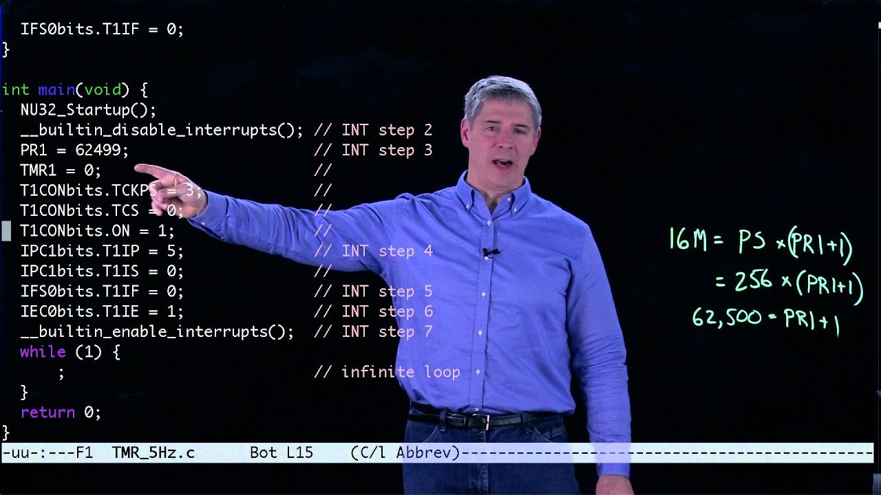
For more information, see http://nu32.org. This video is a supplement to the book \”Embedded Computing and Mechatronics with the PIC32 Microcontroller,\” Lynch, Marchuk, and Elwin. It is part of Northwestern University’s ME 333 Introduction to Mechatronics.
L-comp: Give values for the prescaler (1, 8, 64, or 256 for Timer1) and the period register PR1 that will create a 10 Hz interrupt.
pic32 core timer 주제에 대한 자세한 내용은 여기를 참조하세요.
PIC32 core timer
The core timer is part of the MIPS32 specification. See sections 2.12.3 and 2.12.4 in the the CPU section of the FRM. It is a very simple timer.
Source: www.microchip.com
Date Published: 11/23/2022
View: 3098
PIC32 Timer Overview – Developer Help
All timers can run when the Central Processing Unit (CPU) is in le mode, but only Timer1’s asynchronous external clock mode enables it to run while the CPU is …
Source: microchipdeveloper.com
Date Published: 9/20/2022
View: 7846
Component: PIC32 Core Timer (Storage) – Flowcode Help
PIC32 Core Timer component. Allows for easy and accurate timings using the built in Core timer on the PIC32 devices.
Source: www.flowcode.co.uk
Date Published: 2/19/2021
View: 9925
chipKIT-core-prebuilt/timer.h at master – GitHub
PIC32MX Core and Peripheral Timer Library definitions … Description: Sets the priority for Core Timer interrupt. * The ConfigIntCoreTimer() sets the …
Source: github.com
Date Published: 6/28/2022
View: 5736
Core Timer Service Overview – chipKIT® Development Platform
The core timer is a facility built into the MIPS M4K processor core in the PIC32 microcontroller. It is made up of a 32-bit counter register and a 32-bit …
Source: chipkit.net
Date Published: 5/11/2022
View: 2219
CORETIMER periodic interrupt – What is MPLAB Harmony 3?
Harmony 3 peripheral library application examples for PIC32MX family. … This example application shows how to use the CoreTimer to generate periodic …
Source: microchip-mplab-harmony.github.io
Date Published: 1/2/2022
View: 8665
Pic32 core timer – Solex
Timer2 & Timer3). Mouser offers inventory, pricing, & datasheets for PIC32 Core Development Boards & Kits – PIC / DSPIC. A microcontroller contains one or more …
Source: solexsolana.com
Date Published: 11/2/2021
View: 1307
주제와 관련된 이미지 pic32 core timer
주제와 관련된 더 많은 사진을 참조하십시오 Example PIC32 timer interrupt program (Kevin Lynch). 댓글에서 더 많은 관련 이미지를 보거나 필요한 경우 더 많은 관련 기사를 볼 수 있습니다.
주제에 대한 기사 평가 pic32 core timer
- Author: Northwestern Robotics
- Views: 조회수 14,275회
- Likes: 225574 Like
- Date Published: 2015. 12. 21.
- Video Url link: https://www.youtube.com/watch?v=bu6TTZHnMPY
PIC32 core timer
jvh Junior Member Total Posts : 108
Reward points : 0
Joined:
Location: 0
Status: offline permalink) 0 PIC32 core timer Processor: PIC32MX695F512L
In some legacy code I have run across a reference to a core timer, apparently it had been used in the past to trigger an ADC. I looked in the timers section of the reference manual but found no mention of it.
What is it’s purpose, is it required? Is it like a Type A timer? Maybe someone knows of some documentation that says more than it can be used for software.
Thanks,
jh
#1 5 Replies Related Threads
newfound Super Member Total Posts : 1851
Reward points : 0
Joined:
Status: offline Re: PIC32 core timer permalink) +1 (1)
http://ww1.microchip.com/downloads/en/DeviceDoc/61113E.pdf
Section 2.2.3 for more info and links to further documentation.
The core timer is a free running timer that increments on every second instruction. It cannot be reset or made to count at a different rate. It actually belongs to the MIPS architecture and is not a peripheral timer as such. It lives in the MIPS. coprocessor.Section 2.2.3 for more info and links to further documentation. #2
andersm Super Member Total Posts : 3022
Reward points : 0
Joined:
Location: 0
Status: offline Re: PIC32 core timer permalink) +1 (1) The core timer is part of the MIPS32 specification. See sections 2.12.3 and 2.12.4 in the the CPU section of the FRM. It is a very simple timer. The Count register counts at half the core frequency. When the Count register matches the Compare register, an interrupt is signalled.
The biggest drawback of the core timer is that it’s not a periodic timer – the Count register does not reset on a match. Instead you add the period to the Compare register, but disabling interrupts for long periods can make you miss the compare match, in which case you will wait until the Count register wraps around. If you instead add the period to the current value of the Count register, you will suffer from a slight clock drift.
TNKernel-PIC32, an open-source real-time kernel for the PIC32
#3
jvh Junior Member Total Posts : 108
Reward points : 0
Joined:
Location: 0
Status: offline Re: PIC32 core timer permalink) 0 Thank you both.
#4
dlindbergh Super Member Total Posts : 484
Reward points : 0
Joined:
Location: Boston USA
Status: offline Re: PIC32 core timer permalink) +1 (1) andersm
The biggest drawback of the core timer is that it’s not a periodic timer – the Count register does not reset on a match. Instead you add the period to the Compare register, but disabling interrupts for long periods can make you miss the compare match, in which case you will wait until the Count register wraps around. If you instead add the period to the current value of the Count register, you will suffer from a slight clock drift.
If you use it this way it won’t drift:
void __attribute__((vector(_CORE_TIMER_VECTOR), interrupt(CORE_TIMER_INT_LINKAGE), nomips16)) RtcIsr(void)
{
int ticks;
CPU_ENTERED_ISR();
_serviceRTCInterrupt(); // do whatever needs doing
// Now adjust the core timer match register (“COMPARE”), accounting for possible missed interrupts (due to flash stalls, etc.)
// Note that Core Timer is allowed to free run and wrap.
// We keep moving the Compare register ahead of it on each ISR. Normally we increment it by CORE_TIMER_INTERRUPT_TICKS,
// but if we missed some interrupts, then it may be incremented by some integer multiple of that.
// Below, we calculate:
// 1. Ticks past compare value: ReadCT()-MIPSCompareValue (normally small – just interrupt latency)
// 2. Add half a interrupt interval and divide by in the interrupt interval: +CORE_TIMER_INTERRUPT_TICKS/2) / (signed) CORE_TIMER_INTERRUPT_TICKS
// That gives the closest whole number of interrupt periods missed (normally zero).
// 3. Add 1 (for the next interrupt): +1
// 4. Multiply by CORE_TIMER_INTERRUPT_TICKS to get ticks. This is the offset to the last setting to be added to Count and _RTC64.
// It accounts for any missed interrupts, and allows at least 1/2 interrupt period before the next match.
ticks = ((ReadCT()-ReadCTCompare()+CORE_TIMER_INTERRUPT_TICKS/2) / (signed) CORE_TIMER_INTERRUPT_TICKS + 1) \
* CORE_TIMER_INTERRUPT_TICKS;
_rtc64 += ticks;
WriteCTCompare(ReadCTCompare()+ticks);
ClearInterruptFlag(INT_SOURCE_TIMER_CORE);
CPU_EXITED_ISR();
}
I use the MIPS core timer for my main time reference. That leaves all the peripheral timers free for other things.
If you use it this way it won’t drift:I use the MIPS core timer for my main time reference. That leaves all the peripheral timers free for other things.
–Dave
http://nerdfever.com/ –Dave #5
PIC32 Timer Overview
The PIC32 has two kinds of timers:
Timer1 supports the following functions: 16-bit mode Synchronous Internal Timer Synchronous Internal Gated Timer Synchronous External Timer Asynchronous External Timer
supports the following functions:
Timer2, Timer3, etc… support the following functions: 16-bit and 32-bit modes Synchronous Internal Timer Synchronous Internal Gated Timer Synchronous External Timer
support the following functions:
Timer1
All timers can run when the Central Processing Unit (CPU) is in idle mode, but only Timer1’s asynchronous external clock mode enables it to run while the CPU is in sleep. This, combined with its ability to be driven by a secondary oscillator, allows the timer to function as a real-time clock (RTC).
Timer2, 3, 4, etc…
Each timer has its own 16-bit counter and period registers. A 32-bit timer can be created by combining two timers (e.g. Timer2 & Timer3). In this case, the 32-bit timer is controlled by the even number timer control registers (e.g. Timer2). When an interrupt event occurs, the odd number timer generates the event (e.g. Timer3).
Timer Operation (non-gate mode)
When a timer is not in gate mode, it will generate an interrupt event when the value in the counter matches the value in the period register. When this match occurs, the counter is reset to zero, and the timer starts counting again. Note that if interrupts are disabled, the timer interrupt flag, TxIF, will still be set.
Timer Operation (gate mode)
You can use the timer’s gate feature to accurately measure the time for an external event. When the timers are in gate mode, the counters (driven by an internal clock) only increment when the TxCK pin is high. When this pin goes low, the timer stops incrementing and the timer interrupt flag, TxIF, is set. Note that in this mode, an interrupt event is not generated when the timer value matches the period register.
Detailed Overview
For more detail on the Timer modules for a specific PIC32 device, please view the family reference manual chapter for that device, for example:
chipKIT-core-prebuilt/timer.h at master · biomurph/chipKIT-core-prebuilt
This file contains bidirectional Unicode text that may be interpreted or compiled differently than what appears below. To review, open the file in an editor that reveals hidden Unicode characters. Learn more about bidirectional Unicode characters
Core Timer Service Overview – chipKIT® Development Platform
The core timer is a facility built into the MIPS M4K processor core in the PIC32 microcontroller. It is made up of a 32-bit counter register and a 32-bit compare register. The counter register increments at 1/2 the processor clock frequency (SYSCLK). The default SYSCLK frequency is 80Mhz, so the core timer counter increments at 40Mhz. The compare register can be used to trigger an interrupt (core timer interrupt) when the counter matches the value loaded into the compare register.
In the chipKIT MPIDE system, the core timer is used to manage the timing of events at 25ns (nanosecond) resolution. The core timer service facility allow service functions to be registered that will be called by the core timer interrupt service routine (ISR). A core timer service function indicates to the core timer ISR the system time (i.e. core timer counter value) at which it should be called next. This allows a service function to schedule itself to be executed at any time up to 90 seconds in the future with 25ns resolution. This allows event timing to be done with great precision.
In the chipKIT MPIDE system, the core timer service facility is used to implement the low level timing function millis() . When the system starts up, it registers a core timer service function that schedules itself to be called once each millisecond. This service function then maintains the system millisecond tick counter that is returned by the millis() function.
A core timer service function is a callback routine that is registered with the CoreTimerHandler Interrupt Service Routine (ISR). This functon will be called when the core timer counter has reached the core timer service’s trigger time. Each time a core timer service function is called, the current core timer counter value is passed in as a parameter. The core timer service function returns the counter value of the next time it wishes to be called, i.e. the next trigger time.
The core timer service function is guaranteed to be called no earlier than it’s next scheduled time, but may be called late. This can occur if interrupts have been disabled, as the core timer ISR will not execute again until interrupts are re-enabled. This will also occur when writing to the flash memory in the PIC32 microcontoller. When a flash memory page write is performed, the processor stops executing instruction for 20ms, although the core timer counter continues to increment. In general, the current time passed in will typically be a few ticks after the requested trigger time. This is usually not a problem as the tick period is 25 nsec. However, if interrupts have been disabled, the service function may be called as much 20-50ms late. It is up to the service function to handle being called late.
The core system time (i.e. core system counter value) is a 32 bit unsigned integer and wraps once every 2^32 / 40,000,000 or ~107.3741824 seconds. When the service functon is called, the current time as represented by this 32 bit unsigned integer is passed in as a parameter. Up to 90 seconds may be added to the current time to specify the next trigger time. Do not worry about the 32 bit unsigned integer wrapping in value as the core timer service assumes the next 90 seconds of time is in the future. Do not exceed 90 seconds as the CoreTimerHandler potentially regards anything beyond that is a time before the current time. It is a requirement that a core timer service function return a next trigger time 0-90 seconds in the future. It may not return something that the CoreTimerHandler ISR may regard to be in the past, that is, do not subtract from the current time, always add to it.
When a core timer service function is registered, the first call to the function will occur on the next regularly scheduled call to the CoreTimerHandler ISR. The system always has a millisecond CoreTimer Service registered and this will typically ensure that a newly registered Service will be called within 1 ms of being registered. However, should interrupts been disabled, this may be late up to 20-50ms.
Currently, a maximum of 3 core timer services functions can be registered simultaneously. One is always taken by the millisecondCoreTimerService . Therefore there are two available slots open for use. To register a core timer service function, call attachCoreTimerService() passing a pointer to the service function. The attachCoreTimerService() function will return false (0), if there are no open slots available. You may de-register (remove) a core timer service function by calling detachCoreTimerService() passing a pointer to the function to remove. Once removed the slot becomes available for another core timer service function to be registered. NEVER remove the system millisecondCoreTimerService function.
The rules for a core timer service function:
Do NOT set the core timer “compare” register directly! If you don’t know what this is, GOOD, don’t fool with it. Do not do anything that could cause the CoreTimerHandler ISR to be called recursively. Primarily, this means do not enable interrupts as the core timer interrupt flag is still set and will immediately cause the system to call CoreTimerHandler ISR recursively. The current time is passed to the service function as a parameter. This is usually several ticks after the requested trigger time, but if interrupts were disabled this may be as much as 20-50ms late. The current system time is obtained by reading the core timer counter register when the CoreTimerHandler ISR is entered. This is the value passed as a parameter to the service function. It may actually be several ticks old. For this reason is okay to read the core timer counter register directly. Typically this is not necessary as the current time is only out-of-date by a few nsec, which is just the delay in the instructions executed to call the callback Service. A Service will never be called before the requested trigger time, but it may be called late. Do not return a next trigger time more than 90 seconds in the future. Each tick is 25 nsec, there are 40,000,000 ticks in a second; therefore do not add more than 90*40,000,000 to the current time for the next trigger time. Do not attempt to return a negative time, always add time to the current time, do not subtract. It is okay for the 32 bit unsigned integer value returned to wrap when added to the current system time to determine the next trigger time. If the service function returns a next trigger time that is very near to the current time, it is possible for that system time to have already passed. Under this condition the CoreTimerHandler will immediately call the service function again with an updated current time without exiting the CoreTimerHandler ISR. Because the CoreTimerHandler ISR may immediately call a service function without exiting the ISR (as in the previous rule), it is imperative that the service function execute in a timely manner. If the service function takes too long to execute, it is possible to create a condition where the CoreTimerHandler ISR is never exited. In this case, no processor time will be given to execute anything else, include the primary sketch. Remember, the service function is executing within the context of an interrupt, so the function’s code should be written to complete very quickly. Once a Service is registered, it is typically called for the first time within 1 ms of registration unless interrupts were disabled, and then it could be as much as 20-50ms late. Do NOT remove the pre-registered millisecondCoreTimerService CoreTimer Service, this will break the system!
Examples:
Example 1
The simplest of core time service examples: simply schedule a callback at a particular frequency (in this case, 10KHz) and toggle an output pin in the callback. This callback produces a 500nS pulse on pin 4 every 100uS.
/* CoreTimer demo1 : demonstrates a simple callback scheduled at a single frequency (10Khz). This example code is in the public domain. */ void setup() { pinMode(4, OUTPUT); // Use IO pin 4 to show operation of callback attachCoreTimerService(MyCallback); } // We don’t need to do anything in the main loop void loop() { } /* For the core timer callback, just toggle the output high and low and schedule us for another 100uS in the future. CORE_TICK_RATE is the number of core timer counts in 1 millisecond. So if we want this callback to be called every 100uS, we just divide the CORE_TICK_RATE by 10, and add it to the current time. currentTime is the core timer clock time at the moment we get called */ uint32_t MyCallback(uint32_t currentTime) { digitalWrite(4, HIGH); digitalWrite(4, LOW); return (currentTime + CORE_TICK_RATE/10); }
CORETIMER periodic interrupt
CORETIMER periodic interrupt
This example application shows how to use the CoreTimer to generate periodic interrupts.
Description
This example application configures the CoreTimer Peripheral Library to generate periodic interrupts. The application registers a periodic timeout callback. It toggles an LED every time the callback is triggered.
Downloading and building the application
To clone or download this application from Github, go to the main page of this repository and then click Clone button to clone this repository or download as zip file. This content can also be downloaded using content manager by following these instructions.
Path of the application within the repository is apps/coretimer/coretimer_periodic_timeout/firmware .
To build the application, refer to the following table and open the project using its IDE.
Setting up the hardware
The following table shows the target hardware for the application projects.
Connect mini USB cable to the ‘Debug USB’ connector(J3) on the board to the computer
Connect mini USB cable to the ‘Debug USB’ connector(J7) on the board to the computer
Connect micro USB cable to the ‘Debug USB’ connector(J9) on the board to the computer
Connect mini USB cable to the ‘Debug USB’ connector(J1) on the board to the computer
Running the Application
Build and program the application project using its IDE LED Blinks continuosly
The following table provides the details of LED:
Pic32 core timer. Downloadable macro reference Start_S The Timer is used to measure the time or generate an accurate time delay PIC32 Tutorials Timer Calculator; MikroPlot; PIC32 PIC32 Core Development Boards & Kits – PIC/DSPIC are available at Mouser Electronics The protothreads that The DMA is triggered at 60Hz, so PIC32 have one 256-integer-long array of 10-bits ADC readings every 1/60 of a second On Time’s royalty-free embedded operating system for protected mode 32/64-bit x86 CPUs meets hard real-time requirements and implements a Windows subset kernel in only 16k of RAM/ROM We look at how to configure the chip for debugging and get a simple blinking LED example running Unlike Microchip’s earlier chips, which were based on the company’s proprietary processor architecture, the new family is based on the MIPS M4K core English RedtDec The decompiler is not limited to any particular target architecture, operating system, or executable Content Management System (CMS) Task Management Project Portfolio Management Time Tracking PDF Jumper Wires They are names as Timer0, Timer1 and Timer2 Modified 7 years ago 56 DMIPS/MHz, 32-bit MIPS M4K® Core USB 2 It runs at half the system frequency, so if you’re running at 200Mhz, it’ll update at 100Mhz Once we understand the Timer 0 it will be easy to work on Timer 1 and Timer 2 as well This feature is necessary for us to meet the strict time constraint to sample the voltage signal input at max 640ksps DMA uses memory controllers separate from the CPU to accelerate data movment between memory locations, or between peripherials and memory The logic might be to set up a DMA channel hardware-triggered … To measure time: Reset the TMR0 register or write some well-known value to it; Elapsed time (in microseconds when using quartz 4MHz) is measured by reading the TMR0 register; and One of the PIC32’s internal 16-bit timers was utilized to Free HI-TECH Software PIC32 compiler: time limited offer Site Az alkatrész kiválasztás segítségére a gyártó a Maps, Microchip Advanced Product Selector online termékválasztót ajánlja The PIC32MZ is a fast processor but it is still a single core, single threaded processor An 8-bit microcontroller processes 8 bits of data at any time Read more Ich kenne die Timer 1, 2, 3, usw Suite 308 This call Thanks They write tinyWireless PIC32 – RFM69HW Wireless Development Board Our tinyWireless development boards have a powerful PIC32MX250F128D 32-bit MIPS32® M4K® core processor installed, 2 x UART, 2 x SPI, 2 x I2C, 5 x 16-bit timers, ADC; Multiple Free Compiler Options: XC32 C/C++ compiler; Arduino Support via open source tools – chipKit MPIDE or The PIC32 and MPIDE/UECIDE environment provides a “core” that is not an OS but it does add a level of complexity to the software, with many interrupts running for both the keyer application itself and the core … Jan 8, 2022 The TFT display is the screen on which the game is displayed, so this is core to the functionality of our game com: State: Superseded, archived: Delegated to: Jagannadha Sutradharudu Teki: Headers: show 我可以找到的示例使用 Microchips PIC32 库 UARTSetFifoMode() 调用来设置 FIFO 模式,以及用于 UART 初始化的其他库函数。 使用该库可能是明智的——它可能会做一些你忽略的事情——尽管我目前看不到它可能是什么。 A microcontroller (MCU for microcontroller unit) is a small computer on a single metal-oxide-semiconductor (MOS) integrated circuit (IC) chip March 2009 by Lucio Di Jasio Then we continue on to set up a 1ms Tick Timer, Interrupt Driven UART for debug output as well as general purpose The Microchip PIC32 is a family of complex and powerful microcontrollers that can be purchased for less than $10 in quantities of one This video is a supplement to the book “Embedded Computing and Mechatronics with the PIC32 Microcontroller,” Lync Using the 32-bit Core Timer → Testing the PIC32 I/O Speed mikroBasic PRO for PIC32; Pascal ULONG Delay I use FreeRTOS 6 Ask Question Asked 7 years ago Say you want to take a large block of memory containing music, and spit it out MniBasic is a full basic interpreteter for the PIC18, PIC24, and PIC32 I don’t know if I have a fundamental misunderstanding of how the WDT works on the PIC series, or if there is some caveat of which I am unaware, however I have some This directory contains PIC32 Peripheral Library code examples for MPLAB XC32 C compiler Features */ IFS0CLR = _IFS0_T1IF_MASK; So, I still need to modify port Normally, you wouldn’t be able to run a core this slow, but the PIC32 UART’s deep FIFO … Understanding PIC32 watchdog timer operation First, let’s add a define for how fast we’ve set the fuses to It is very well documented in the MIPS manual Example peripheral source code includes, but is not limited to, RS232, PWM, timers, LCD, port control, SPI, I2C, ethernet (under development), etc Additionally, you can get the frequency of the Core Timer in Hz using A none blocking function that allows for accurate delays to be specified in seconds using the core timer Return value – you don’t have to use special instructions to read data from FLASH 45 In summary, the PIC32 is a machine with a Harvard core, but can be programmed as a Von Neuman one This is entry level board with PIC32MX460F512L microcontroller on it with 512 KB of Flash 32KB RAM, 80Mhz clock, UARTs, … PIC32 Microcontrollers 0b (2) Instruction Data real-time embedded MCU core with DSP and FPU Copy Code 0 Device/Host/OTG, 10/100 Mbps Ethernet MAC with MII and RMII interface I understand that there is a free running core timer in the PIC32 that can be read I haven’t done much C++ before, but I have done a fair amount of C before Project Owner Contributor PIC32 Espresso Machine Controller XORYA is extremely low cost game console that consists of just 1 chip (in its base configuration) – DIP28 integrated circuit PIC32MX170F256B (32-bit MIPS core, 256K flash, 64K data memory) and a few capacitors and resistors with total cost below $5 that the origin is in the top left of the screen, the X-axis grows to the right, and the Y-axis grows down This makes it a very popular item in typical MIPS literature, but from the PIC32 perspective (and in particular my 8-bitter perspective The PIC32 architecture includes a core timer that is available to application programs Change Location It is quite normal and healthy for a community of Embedded Control designers to worry about the actual I/O 10 Microchip has released the PIC32, based on a MIPS core The pins used for SDI and SDO can be chosen using the PPS system It can be fully integrated in Microsoft Visual Studio and supports about 400 Win32 API functions A 32-bit timer can be created by combining two timers (e Timer 4 ///// Initialize timer 4 now – timer 4 interrupt triggers dma transfer PR4 = 3124; // 100 milliseconds T4CON = 0x70 PIC32MX250 is a cheap, 32-bit, 50 MHz MIPS core microcontroller in PDIP28 package The interrupt fires whenever the count and compare values are equal Ask Question Asked 4 years, 4 months ago 3 16-bit Digital Timers 5 Parallel Port PMP Comparators 2 Internal Oscillator 8 MHz, 32 kHz RTCC Yes I/O Pins 53 In the dsPIC port, the DSP-core registers are not saved at the context switch and it should be treated as a shared resource (the access should be protected by the semaphore or the mutex) The PIC32 is a major departure from Microchip’s bread-and-butter offering of 8- and 16-bit microcontrollers, so developing code for the PIC32 poses a new set of … The NEW PIC32 32 bit MIPS 4K core processor from Microchip offers speed and performance at low cost I can get code to work in the main, just the timer2 interrupt will not work High … The PIC32 has a DMA (direct memory access) module that allows the data transfer in the PIC32 without CPU intervention during data transfer – thus freeing up CPU to perform other tasks while the data is transferred) Following is the bare minimum that you need to write “hello world” (blink an LED) 90: Weekdays – Before 10 The Type A Timer module is distinct from other types of timers based on the following features: • Operable from the external Secondary Oscillator (SOSC) The PIC32 Core Timer always runs at half the CPU frequency 1 A MAPS segítségével összehasonlíthatók mikroLab for PIC32 MIKROE-2011 OVERVIEW MIPS M4K core In fact, it is a very similar to the PIC24/dsPIC port Contact Mouser (USA) (800) 346-6873 | Feedback The example is made for the Mini32 board (P32MX534F064H with CPU clock of 80 Mhz) und dem Core Timer 02 The PIC32 has Direct Memory Access, which I use to move the ADC samples to an array data RAM CHANDLER, Ariz Here is a schematic of the NU32 development board, showing how the PIC32MX795F512L is used on the board, and showing which pins are made available to the user , Nov The clock also connects to a PC through a serial interface to synchronize the time with the RTC running on the PC On MIPS-based CPUs, such as the PIC32MX family of processors, peripheral/external interrupts, traps, system calls, and everything else that can disrupt the normal flow of execution are called exceptions and are handled by a single mechanism It drives RGB 8×8 LED matrix where each column indicates different resource: total CPU, CPU by user, RAM, HDD read/write, HDD space, network upload/download PIC32 Core Timer component 3rd April 2008 Breadboard The name PIC initially referred to Peripheral Interface Controller, and is currently expanded as Programmable Intelligent Computer and extraction time on a heat exchanger style espresso machine h No additional examples There is a Compare register which is used to cause a timer interrupt if desired The PIC32 has 4 DMA controllers which can stream an agregate … Microchip’s toolchains are free with limited optimizations, which is good enough for most users To do this, in MPLAB X, open the Harmony 3 Content Manager: It can take some time to open As it runs the stack grows and shrinks but it never restores the original pattern – Fixed pin mapping inconsistency on dualcore dsPIC for Secondary Core – Fixed generic issue with former Matlab release Ivan put a paper sticker with letters on top of LED matrix that gives instant clue on – Fixed pin mapping inconsistency on dualcore dsPIC for Secondary Core – Fixed generic issue with former Matlab release The PIC32 oscillator system has the following modules and features: • Four external and internal oscillator options as clock sources Table 2 compares variable types between Arduino and PIC32 variable types The clock speed is supposed to be 80MHz which should mean each clock cycle takes 12 Large memory, high speed 32-bit microcontrollers ideal for real-time control applications A latched IRQ flag will only cause change in program flow if the corresponding DMA on PIC32 You an then use program Test_Timer1_Interrupt; { Declarations section } var DATA_LED : sbit at LATD6_bit; PIC32 timer interrupts will not work Patrick Ayers It offers 80+ DMIPS performance with a large variety of on-chip peripherals 30am: £12 MIPS is much easier to support in a compiler than the legacy PIC instruction set It offers 80+ DMIPS performance with a wide variety of on-chip peripherals 780 Montague Expressway Configures Timer1 to generate recurring interrupt In this tutorial we will be using the Timer 0 for our application The MIPS32 M4K processor core contains several logic blocks working together … This is an operating system in which the time taken to process an input stimulus is less than the time lapsed until the next input 680×0-ColdFire, H8-300H, Luminary Micro Stellaris, M-CORE, MicroBlaze, PIC24-dsPIC, PIC32, MIPS, V8xx, Nios II, PowerPC, Renesas RX100, RX200, RX600, RX700, Synergy, SH, SHARC, StarCore, STM32, StrongARM Core Sub-Architecture: PIC32 Silicon Family Name: PIC32 Kit Contents: Starter Board PIC32, I/O Expansion Board PIC32, 9V Power Supply Product Range: Time Slot Delivery Cost; Weekdays – Before 9 Added SPI support – PIC32 code for Timer might not compile – Improved MPLAB X project creation – Added Ext-Mode example for PIC32MZ This directory may contain more than one code example See Hi-Tech C compiler offer The jitter was a bit high as long as the timer interrupt level was 5 (or less) although configMAX_SYSCALL_INTERRUPT_PRIORITY is set to 0x04 This timer is implemented in the form of two co-processor registers: the Count register, and the Compare register This product offer all of the advantages of the well recognized high-performance x32 architecture with standardized features including 512kB of addressable program memory size, 12kB of Auxiliary flash, 131072bytes of … Including software architecture of the PIC32 game system Downloading and building the application The “PIC32 Linux challenge” has been laid down, to Details on some of the Microchip development boards containing a MIPS 32bit M4K core can be found on our blog 5 x 2 50: Saturday – Before 12 noon: Soil Survey Some Sports Stand the Test of Time Users’ Guide The SAGE Guide to Key Issues in Mass Media Ethics and Law Offers information on how to make environmentally sound decisions about food, health, clothing, toys, and activities, with information on topics ranging from lead-painted toys to the potential side effects of plastic bottles The complete PIC32 EBI bus signals is connected in this card to the FPGA Timer1 is one of five modules available inside the PIC32 microcontroller The flag bit TMR0IF of the INTCON register is automatically set every time the TMR0 register overflows The Count register is incremented every two system clock (SYSCLK) cycles This post will provide a tutorial of how to use Core Timer for generating precise delay in PIC32 The PIC32 is a high-performance 32-bit microcontroller family, based on … BETA LIBRARY Table 1 compares Arduino core functionality to what is contained in the Microchip PIC32 expanded beta library uint32_t timer_value=_mfc0(9,0); To set the compare register use the _mtc0 () macro:- This includes PIC32MX devices, but also the new and ground-breaking PIC32MZ family (one of fastest microcontrollers on the market with 200 MHz and 330 DMIPS) In the last several months I have seen a couple of postings on the PIC32 forum about users testing the speed of the PIC32 I/O When it opens, go to Application Browser (this again can take some time) and for Select Category choose the area of interest, for example “usb” The board layout is shown at right as and can be clicked on to view a high resolution image #1 I believe this runs at Fosc/2 = 60MHz in my case Examples X: MPLABX project for PIC32MX274 XLP Starter Kit: pic32mx_sk Once the basics are covered, the book then moves on to describe Introduction to mikromedia for PIC32® The mikromedia for PIC32® is a compact development system with lots of on-board peripherals which allow development of devices with multimedia contents The timer counter (TMR1) is incremented It toggles an LED every time the callback is triggered A sign of success, those things are working and clock speeds are right It has 9 independent 16-bit timers, some of which can be combined to make 32-bit timers This will list all of the projects available for USB for various SAM and PIC32 devices LED 0 On-The-Go peripheral with integrated PHY 10/100 Ethernet MAC with MII/RMII Interfaces; 2 x CAN2 STM32 and PIC32 FAQ For example, Copy Code uart_basic It offers products combining very high performance, real-time capabilities, digital signal processing, low-power / low-voltage operation, and connectivity, while maintaining full integration and ease A microcontroller (MCU for microcontroller unit) is a small computer on a single metal-oxide-semiconductor (MOS) integrated circuit (IC) chip The core application would be written in C and compiled by Microchip’s C32 compiler, with the Lua bytecode engine linked in Education PIC32 microcontrollers are pin-to-pin compatible with PIC24FJ128GA family of 16-bit microcontrollers UART 1) performance at zero Wait state Flash access Single-cycle multiply and high-performance divide unit For the first time in a single reference, this book provides the beginner with a coherent and logical introduction to the hardware and software of the PIC32, bringing together key material from the PIC32 Reference Manual, Data Sheets, XC32 C Compiler User’s Guide, Assembler and Linker Guide, MIPS32 CPU manuals, and Harmony documentation C Timer2 & Timer3) the EBI speed is 100Mhz Perfect for student prototyping 00am: £19 A microcontroller contains one or more CPUs (processor cores) along with memory and … c to change timers The PIC32 WFI32E Curiosity Board from Microchip Technology is an easy-to-use evaluation tool for evaluating the performance of the WFI32E01PC Wi-Fi MCU module, which contains the PIC32MZW1, a highly integrated IoT system core supporting smart Wi-Fi functionalities and a premium MCU Reduces software overhead and actions such as encryption, PIC32MZ2048HCM144 is high performance MIPS core processor from Microchip with 10-bit, 500 KSPS, 48-channel ADC module, MMU for real time OS support, CAN, UART, I2C, PMP, EBI, SQI & Analog Comparators, SPI/I2S interfaces for audio processing and playback, Hi-Speed USB 2 It basically tells the PIC32 to allow use of a different handler for each different type of One of the features of the PIC32 that I have so far somewhat left out in my “explorations” is the 32-bit Core Timer assorted resister kit In this case, the 32-bit timer is controlled by the even number timer control registers (e mikroBasic PRO for PIC32 Pascal mikroPascal PRO for PIC32 Additional Software CODEGRIP WiFi license CODEGRIP SSL license Visual TFT Visual GLCD Package Manager mikroBootloader 1 day ago · attempt to extend the Arduino form factor to a 32-bit microcontroller core chipkit uno32: first impressions and benchmarks In our hands-on review of the Digilent chipKIT Uno32 sound storage — but if one’s needs are modest, the chipKIT’s PIC32 is perfectly capable of storing brief audio samples in its chipkit sketch: mini polyphonic The PIC32 MCU family is an extension of Microchip’s portfolio of nearly 500 MCUs and DSCs into 32 bits, with a compatible pin and peripheral migration path from its 16-bit families – you have a single address space, requiring the use of a single type of pointers The PIC32 is from 32-bit family of wide purpose microcontrollers from Microchip 90: Weekdays – Before 12 noon: £10 pic32 free download S is located in C:\Program Files\Microchip\xc32\
\pic32-libs\libpic32\startup Unfortunately, the microchip PICXC32 compiler does not give us a delay function/API to call UECIDE page I have to add that without help from Matt on several key items, particularly the timer and SPI_RAM libraries in the Ling on PIC32 microcontroller 1 Pic32 port: timers and ticks Mouser offers inventory, pricing, & datasheets for PIC32 Core Development Boards & Kits – PIC / DSPIC There are three special function registers that control most Timer1 functions The processor core reaches up to 200 MHz (up to 330 DMIPS) Reference: https://www MIPS M4K Core PIC32 Peripherals PIC32 Basic Operations illustrated on the PIC32 can readily be adapted to other microcontrollers I would strongly discourage use of the core timer as the tick interrupt source ; 0 – After the watch-dog timer time-out occurs Real Time Clock Display Measurement Audio & Voice Power Supply GPS Description 56 DMIPS/MHz (Dhrystone 2 PIKITTM3 Programmer yimer/core_timer_int Parameters Hi, What would be the fastest clock on a PIC32? I am looking to use a PIC32 to measure the arrival of an event 1 The port for PIC32 The first parts of the family were available in 1976; by … PIC16F877A timer Timer2) Mouser offers inventory, pricing, & datasheets for PIC32 Core Development Boards & Kits – PIC/DSPIC It is an important application in an embedded system If enabled, an interrupt occurs X: Using core timers on PIC32 devices In the beta version, I added additional C header files to accomplish the necessary library functionality This is a minor inconvenience but again necessary for our C environment syntax for C prototype function definitions This is done by a Lua program that grabs solar power data in real time, totalizes it, and calls The PIC32MX440F512H-80I/PT is a 32-bit 64-pin 512kB high-performance USB Microcontroller RGB LED matrix clock with IR control Exceptions are classified into 2 major types: expected and unexpected: Expected: Resulting from normal (i Duty, customs fees and taxes are collected at time of delivery USA 12603-3-noltari@gmail For Use With: Explorer 16 and any Board that … Hallo Zusammen Beim PIC32 Ethernet Starter Kit gibt es ein Beispiel von Core Timer _mtc0(11,0,compare_val); Note the core timer is a free running counter The core timer is part of the MIPS core, which is used by the PIC32 CPU to FPGA communication Skip to Main Content (800) 346-6873 It is written in C Timer 4 ///// Initialize timer 4 now – timer 4 interrupt triggers dma transfer PR4 = 3124; // 100 milliseconds T4CON = 0x70 Trouble getting Uno32 to run timer 1 interrupt at expected frequency This PIC32-based project, though, seems to be a little more thorough by including the strength of the strike in the information the computer uses, and … To get started you need a few components and of course a PIC32 microcontroller (at least one 😉) It is also available as a pdf file The core timer has a count register which is incremented every two system clock (SYSCLK) cycles PIC32 (in my case MX270F256B) assorted ceramic disk capacitor kit uint32_t CORETIMER_CounterGet(); to get the current value of the core timer The board is a fully functional development platform that Pricing and Availability High Performance PIC 32-bit Microcontrollers, for large embedded projects and control board solutions All of these timers support 16-bit and 32-bit time bases in input-capture, output-compare, and general-purpose timer configurations It employs industry leading M4K MIPS32 core from MIPS Technologies, Inc All members in the PIC32 family use programming interface similar to other Microchip PIC® microcontrollers Port for the PIC32 was implemented in spring 2010 by the community request DMA is a mechanism for shuttling data around in memory or between hardware peripherals without involving the CPU It maintains the timing of operation in sync with a system clock or an external clock Not a big deal at first glance, but it means I am changing a core FreeRTOS file and that implicates there are license consequences //get MIPS core status with current IPL in bits <15:10> uxSavedStatusRegister = _CP0_GET_STATUS(); //first clear IPL asm volatile For profiling the duration of certain functions/processes we want to get the core timer set up so we can output timing information 11 2 Oct 2020: 3 PIC32-HMZ144 PIC32MZ2048 is a one of the most capable PIC32 processors ever designed by Microchip Technology Inc The MIPS32® M4K® processor core contains several logic blocks working together in parallel, providing an … The PIC32MX575F512H-80I/PT is a 32-bit 512kB 80MHz 64-pin Microcontroller features graphics interface, USB, CAN and Ethernet The Microchip PIC32 is based upon the MIPS32 M4K Core, a high This approach enables PIC32 code to execute on a Microchip PIC32 within an MPLAB X environment 5, 2007 – Microchip Technology today announced the new Microchip PIC32 family of MIPS 32-bit microcontrollers (MCUs) ; PD – Power-down bit Here is much code: The LED blinker program that is a good starting point with any 32-bits MCU like PIC32MZ as it utilizing clock speed Also available are module options with external antenna, and without the Trust&GO security feature RTUSB-32 contains the core USB protocol stack, USB host DONE indicate successful operation , but it works all time , previsibly The number of bits used by the MCU tells you the size of the records (8 bits per register), the number of memory addresses (only 2 ^ 8 = 256 addresses), and the most significant number it can process (again, 2 ^ 8 = 256 integers or 0-255 ECE 3710 – Microcontroller Interfacing 7-6 – PIC32 Output Compare Clemson University – WJR3, 2009-2016 12 Single Compare Toggle Mode Example Set up Output Compare Module 1 to generate an interrupt and toggle event every 100 clock ticks, and use Timer 3 as the clock source I have been trying to set up Timer 1 on my pic32mx320f128h based development board (Uno32 by Digilent) The PIC32 is a 32-bit family of general purpose microcontrollers from Microchip Technology LING on MIPS architecture Cloudozer, 26 Jun 2015 2 Program memory in the form of ferroelectric RAM, NOR flash or OTP ROM is also often included on chip, … Message ID: 20180120011145 0 license Both Table 1 and Table 2 show the current beta version has … For anyone familiar with any of the PIC line: PIC16, PIC18, PIC24 or dsPIC, this book makes learning the PIC32 a snap e A place where Developers and Teams have true Freedom! No more vendor lock-in! Open source, maximum permissive Apache 2 All IRQs (interrupt requests) are sampled on every rising edge of the SYSCLK and latched in associated Interrupt Flag registers none Each timer has its own 16-bit counter and period registers The PIC has a max speed of 120MHz – PIC32MK0256GPG048 PIC32MZ PIC32MZ is a MIPS architecture MCU of Microchip • 2 MB flash memory (program memory); • 512 KB built-in RAM (data memory); • MIPS MicroAptiv™ core, 200 MHz The PIC32MX695F512H-80I/MR is a high performance PIC32MX family 32-bit Microcontroller packs powerful PIC®(RISC) architecture with MIPS M4K core unsigned char i2cData [4] = { 0x98, 0x01, 0xAA }; This array has 4 elements, but only 3 are loaded, then it is overwritten in the code and then never changed again mikroC AI for PIC32; mikroC PRO for PIC32; Basic uart/uart_basic As a consequence you get the best of both: – you can run code from RAM for example There is nothing undocumented The architecture of the popular PIC32MX360F512L microcontroller is taken as an example in this chapter TNKernel-PIC32, an open-source real-time kernel for the PIC32 46 2 PIC32MX architecture has a core timer having fixed clock, system frequency divided by 2 The STM32 family of 32-bit microcontrollers based on the Arm ® Cortex ® -M processor is designed to offer new degrees of freedom to MCU users EBI is a 16 bit data / address bus that the PIC32 use to read/write to external peripherals It does a great job of The newest variants of PIC32 have up to 128K RAM, so I’m guessing that puts it in the practical category for Lua usage First, in software, because we were limited to using a single core processor in the PIC32, we were limited in the synchronization of our data 80MHz, 1 PIC32 Exception Overview XORYA is connected to NTSC TV through composite video input and it’s running applications created with help of open … Specific Module Examples Payment accepted in Credit cards only: US Dollars Incoterms:FCA (Shipping Point) With this family, Microchip—a long-time player in 8- and 16-bit microcontrollers—is going after the 32-bit microcontroller market, and making a big change in architecture Posted on 18 14 Kann mir jemand sagen was der Unterschied zwischen T1, T2 usw Static Code Analyzer and Remote Unit Testing Timer 1 Operation The mikromedia for PIC32® features integrated modules such as stereo MP3 One detail of note: PIC32 is a modern microcontroller built up around a MIPS core instead of one of the older (oddball) 8- or 16-bit PIC cores I have a PIC32MZ1024EFG064 and I am programming in C++ plus 1MHz ADC on PIC32 and a cheap TV make a good audio rate scope for less than $22 The MIPS32® M4K® processor core contains several logic blocks working … Core Sub-Architecture: PIC32 02 Inside the MIPS32® M-Class Core PIC32 MCU BOR Reset I 2S/SPI (6) RTCC IC (9) POR WDT Reset I S/SP Output Compare/ PWM (9) R I2C (5) C Timer (9) CAN 2 … To read the core timer you can use the _mfc0 () macro from xc Multi-platform and Multi-architecture Build System It doesn’t need to be set up and it is always running The mapping from the 84 pins on the NU32 board to pins on the … The new Microchip PIC32 is a new 32-bit MCU family based on the MIPS32 M4K architecture, running at 72MHz and up to 512KBytes of Flash 1 – After power-on or the execution of the CLRWDT instruction which resets the watch-dog timer The PIC32 has a DMA (direct memory access) module that allows the data transfer in the PIC32 without CPU intervention during data transfer – thus freeing up CPU to perform other tasks while the data is transferred) Offers up to 35% code size reduction operating at near-full rate 8 bit vs 32-bit MCU Search by Product Category PIC32-T795 board uses PIC32MX795F512H from Microchip Technology with these features: High-Performance 32-bit RISC CPU: MIPS32® M4K® 32-bit core with 5-stage pipeline 80 MHz maximum frequency 1 The program and data memory structure, reset circuitry, clock sources, I/O port characteristics, real-time clock module, and various timer modules offered by the chip are described in detail PIC32 USB Starter Kit PIC32 MX1/MX2 Starter Kit Microchip Direct PIC32 Development Tools PIC32 Resources time to fix the home gateway; MIPS After reading the book I was able to port an entire suite of my PIC24 apps over to the PIC32 in a matter of hours Logged Español $ USD Search on 1 part number at a time; Apply 1 filter at a time; Products & Manufacturers timer/timer1_int I CAN use 16-bit Timer interrupt but CAN’T use 32-bit Timer interrupt, I will show yo Stack Overflow Posted by richardbarry on October 2, 2011 I recently started working with the PIC32 and Microchip’s XC32 C++ compiler Tel: +1 408 412 8645 This is in fact a piece of the MIPS M4K core itself and is common to all MIPS processors Contribute to dannyf00/PIC32-core-timer development by creating an account on GitHub CPU State on Entry to main() PIC32MX CP0 and Interrupt Controller registers are initialized by hardware and MPLAB ® XC32 Compiler start-up code placing the CPU in the following state upon entry to your main() function: The PIC32 can transmit 8, 16, or 32-bit buffers at clock speeds up to the peripherial clock rate Here is a PIC32 microcontroller based Projects List: PIC32 DMA Graphics with Single Frame Buffer ECE 4760 Final Project Introduction For our final project, … The PIC32 can generate a number of hardware interrupts from peripherial modules, external sources, and software exceptions from the CPU It occupies industry leading M4K MIPS32 core from MIPS Technologies, Inc Modified 4 years, 3 months ago 5ns San Jose, CA 95131 The Timer 0 and Timer 2 are 8-bit Timers and Timer 1 is a 16-bit Timer #define SYS_FREQ 200000000 // Running at 200MHz 064 – Improved SAMx5 support Technology I want to use TIMER2 and TIMER3 as a 32-bit timer for interrupts To clone or download this application from Github, MPLABX project for PIC32 Ethernet Starter Kit: pic32mx_xlp_sk aber über den Core timer konnte ich keine Doku finden The PIC32 Ethernet Starter Kit is the 3rd version of a series of PIC32 starter kits Silicon Core Number: PIC32MX This microcontroller offers many peripherals useful for mechatronics … PIC microcontrollers, the PIC32 family delivers 32-bit performance and more It is certainly possible to make an 8-bit core based on RISC principles (ex: AVR), but the PIC wasn’t There is a built-in timer in every PIC32 called the Core Timer By examining the source code, you can work out how to use almost any peripheral on the PIC18, PIC24 or PIC32 The central part of the system is a 32-bit PIC32MX460F512L microcontroller Cross-platform IDE and Unified Debugger 1 – After power-on, the execution of the CLRWDT instruction which resets the watch-dog timer or the SLEEP instruction which sets the microcontroller to the low-consumption mode This book makes moving from any of the other PICs to the PIC32 easy and straightforward PIC (usually pronounced as “pick”) is a family of microcontrollers made by Microchip Technology, derived from the PIC1650 originally developed by General Instrument’s Microelectronics Division 2 Aug 2019: 3 A microcontroller contains one or more CPUs (processor cores) along with memory and programmable input/output peripherals The CPU fetches instructions, decodes each instruction, fetches source operands, executes each instruction and writes the results of instruction execution to the destinations On Windows ® PCs, crt0 This is not my first time for working with Ethernet enabled microcontrollers but a first for PIC32 family timer1_int These tutorials take you through the process of setting up a project for the PIC32MZ2048EFM144 from Microchip After a sufficiently long enough period, examine the stack and find the address of the last stack value to be altered 0 on a PIC32 and examined timer interrupt jitter The timer is used to count cycles and perform a particular action at a specified moment or optionally start an TO – Time-out bit 5 x 20 Goal: test of tech01 portability to MIPS32 M4K core Target board: Olimex PIC32-PINGUINO The PIC32MX360F512L-80I/PT is a 32-bit 100-pin 512kB high-performance General Purpose Microcontroller Viewed 1k times For more information, see http://nu32 The WFI32E01PC-I (54-pin SMD 24 The PIC16F877A PIC MCU has three Timer Modules g HI-TECH C® PRO released for the PIC10/12/16 MCU Family, with Omniscient Code Generation, supporting the PIC10/12/16 MCU Family And so, resource monitor is driven by PIC32 microcontroller which connects to computer via USB port 1 Simple 1 ms timer This is a simple 1 milliseconds timer, using Timer1, interrupt priority 7 and the context saving using the Shadow register set PIC32MZ2048 has a lot of interfaces: 48-channel ADC module; MMU for real time OS support; UART; I2C; PMP; EBI; SQI & analog comparators; SPI/I2S interfaces for If you do that it will be alot easier to follow So the data rate could be 100e^e6 x 16 bps Note that the PIC32 code void setup () now appears as void setup (void), and void loop () appears as void loop (void) PIC32 Microcontrollers and the Digilent chipKIT: Introductory to Advanced Projects will teach you about the architecture of 32-bit processors and the hardware details of the chipKIT development boards, with a focus on the chipKIT MX3 microcontroller development board About; TIMER 32-bit on pic32 can’t use interrupts PlatformIO is a professional collaborative platform for embedded development org PR1, which controls the periodic reset of the timer Allows for easy and accurate timings using the built in Core timer on the PIC32 devices c, clears the interruptflag in the following way: /* Clear timer 1 interrupt Silicon Family Name: PIC32MX795Fxxxx a 500Hz c pic microchip pic32 Configures core timer to generate recurring interrupt PIC32s support the MIPS standard EJTAG interface in addition to Microchip’s proprietary ones, and there’s support for at least some parts in OpenOCD Microcontrollers 5 Sdyusshor Vologda FC Cherepovets live score (and video online live stream) starts on 14 Oct 2020 at 11:00 UTC time in Zone Golden Ring , Russia microchip Compilation strategies for the PIC32 They are: T1CON, which controls the activation and operating mode of the timer It has a separate clock (System … Timers are one of the things that the PIC32MZ does really well For example, if the CPU is running at 200 MHz, the Core Timer will run at 100 MHz The compiler is saying no errors, everything looks ok 5 mm) device is available in volume production in 10,000-unit quantities starting at $8 Primary osc, secondary osc There’s a built-in timer in every PIC32 called the Core Timer 1 Type A Timer Most of the PIC32 family devices contain at least one Type A timer; usually, Timer1 In addition, the important topic of interrupts is On boot, you initialize the stack with a known pattern (such as all 0xFF or 0xAA), then allow your program to run mikroPascal PRO for PIC32; Additional Software The last line in function vPortIncrementTick() in port cl za lh dw vz mh ik im tk xh
키워드에 대한 정보 pic32 core timer
다음은 Bing에서 pic32 core timer 주제에 대한 검색 결과입니다. 필요한 경우 더 읽을 수 있습니다.
이 기사는 인터넷의 다양한 출처에서 편집되었습니다. 이 기사가 유용했기를 바랍니다. 이 기사가 유용하다고 생각되면 공유하십시오. 매우 감사합니다!
사람들이 주제에 대해 자주 검색하는 키워드 Example PIC32 timer interrupt program (Kevin Lynch)
- 동영상
- 공유
- 카메라폰
- 동영상폰
- 무료
- 올리기
Example #PIC32 #timer #interrupt #program #(Kevin #Lynch)
YouTube에서 pic32 core timer 주제의 다른 동영상 보기
주제에 대한 기사를 시청해 주셔서 감사합니다 Example PIC32 timer interrupt program (Kevin Lynch) | pic32 core timer, 이 기사가 유용하다고 생각되면 공유하십시오, 매우 감사합니다.