
You are looking for information, articles, knowledge about the topic nail salons open on sunday near me how to place ground in proteus on Google, you do not find the information you need! Here are the best content compiled and compiled by the https://chewathai27.com team, along with other related topics such as: how to place ground in proteus Ground in proteus, Arduino in proteus, Power in Proteus, Vee in Proteus, Connector proteus, Volts proteus, Function generator proteus, Add Arduino to Proteus
Contents
Where is ground option in Proteus?
Add “ground” : Left Select model selection toolbar icon appears: Left selection GROUND, and in the schematic editor window, left-click , so that the “ground” was placed into the Schematic Editor window .
How do you get VCC and ground in Proteus?
To place a Vcc terminal (the upwards pointing triangle) select the terminals menu, place a POWER terminal and double click it to select Vcc net. For the ground terminal just place a GROUND terminal, it’s already connected to the GND net.
What is the function of ground in Proteus?
As pspice ,multism, proteus maximum in all simulation software gnd is needed to be given in the circuit as all these softwares performs contain voltage probes which measure potentials at any point in the circuit needs a reference potential so the circuit is needed to be grounded just for observing the simulation …
What is terminal mode in Proteus?
Virtual Terminal is a tool in Proteus, which is used to view data coming from Serial Port (DB9) and also used to send the data to Serial Port.
How do I add PCB layout to Proteus?
Proteus has the integrated ARES PCB designing suit. By using this we can easily develop the PCB layout. After simulation save the circuit designing and click on tools then select netlist to ARES. Then a window will open with list of component packages.
How do I add a library to Proteus Arduino?
- Download all library-related files from GitHub. …
- Extract the zip file and navigate to Proteus-master\Arduino\Library.
- Copy both of the files and paste them in one of the following paths: …
- In Proteus, create a new project. …
- Decide where you would like to save your project.
How do you set a power supply in Proteus?
- Pin # 1 is used as input pin and it is connected to supply voltages. It is marked as (VI). …
- Pin # 2 is called common or ground pin. It is marked as (GND). …
- Pin # 3 is the output pin of 7805. If 12 volts are applied to its input than it automatically generates 5 volts on this pin.
How do you put ground in pspice?
Every circuit that is simulated on PSPICE must have a ground node indicated. This is done by entering the ground symbol. To place the ground, select Place→ Ground (or click on the ground symbol on the toolbar). Select the “Source” library and the ground part labeled “0”.
How do you plot a graph in Proteus?
…
- Replace default initial voltage from 1V to X .
- Select DC Sweep Graph Type.
- Right Click -> Edit Properties to edit start/stop values and number of steps.
- Add voltage and current probes at the desired points.
- Drag probes on to the graph. Press space bar to simulate.
How do I add a library to Proteus Arduino?
- Download all library-related files from GitHub. …
- Extract the zip file and navigate to Proteus-master\Arduino\Library.
- Copy both of the files and paste them in one of the following paths: …
- In Proteus, create a new project. …
- Decide where you would like to save your project.
How do you glow a LED in Proteus?
- Step 1: Select component mode.
- Step 2: Click on Pick devices ‘P’.
- Step 3: Scroll down categories to find ‘Optoelectronics’ or alternatively type LED in Keyword. …
- Step 4: Scroll to find the required LEDs according to circuit.
PROTEUS TUTORIAL #1: How to Add Ground, 5V, 3.3V and use DC Voltmeter – YouTube
- Article author: www.youtube.com
- Reviews from users: 43708
 Ratings
 - Top rated: 3.2
- Lowest rated: 1
- Summary of article content: Articles about PROTEUS TUTORIAL #1: How to Add Ground, 5V, 3.3V and use DC Voltmeter – YouTube Updating …
- Most searched keywords: Whether you are looking for PROTEUS TUTORIAL #1: How to Add Ground, 5V, 3.3V and use DC Voltmeter – YouTube Updating This is a Proteus Tutorial about placement of ground in schematic, 5v and 3.3v supply voltages and using a DC voltmeter.Many early users of proteus are confu…how to add ground on proteus, where to find ground on proteus, proteus ground terminal, proteus schematic ground, how to place ground on proteus, how to add 5v on proteus, how to add 3.3v on proteus, how to add voltage supply on proteus, proteus voltage source, how to add voltage soures on proteus, how to have different voltage levels on proteus, where is the voltage meter in proteus, proteus tutorial, voltage supply on proteus, protues ground, proteus gnd
- Table of Contents:

Getting Started with Proteus – YouSpice
- Article author: www.youspice.com
- Reviews from users: 35816 Ratings
- Top rated: 4.3
- Lowest rated: 1
- Summary of article content: Articles about Getting Started with Proteus – YouSpice Updating …
- Most searched keywords: Whether you are looking for Getting Started with Proteus – YouSpice Updating
- Table of Contents:
pcb – How to unhide hidden pins in proteus? – Electrical Engineering Stack Exchange
- Article author: electronics.stackexchange.com
- Reviews from users: 24695 Ratings
- Top rated: 3.9
- Lowest rated: 1
- Summary of article content: Articles about pcb – How to unhide hidden pins in proteus? – Electrical Engineering Stack Exchange Updating …
- Most searched keywords: Whether you are looking for pcb – How to unhide hidden pins in proteus? – Electrical Engineering Stack Exchange Updating
- Table of Contents:
2 Answers
2
Your Answer
Not the answer you’re looking for Browse other questions tagged pcb pcb-design proteus 8051 7805 or ask your own question

Error 403 (Forbidden)
- Article author: www.quora.com
- Reviews from users: 22833 Ratings
- Top rated: 4.4
- Lowest rated: 1
- Summary of article content: Articles about Error 403 (Forbidden) Updating …
- Most searched keywords: Whether you are looking for Error 403 (Forbidden) Updating
- Table of Contents:
PROTEUS TUTORIAL #1: How to Add Ground, 5V, 3.3V and use DC Voltmeter دیدئو dideo
- Article author: www.dideo.ir
- Reviews from users: 49812 Ratings
- Top rated: 4.0
- Lowest rated: 1
- Summary of article content: Articles about PROTEUS TUTORIAL #1: How to Add Ground, 5V, 3.3V and use DC Voltmeter دیدئو dideo This is a Proteus Tutorial about placement of ground in schematic, 5v and 3.3v supply voltages and using a DC voltmeter. Many early users of proteus are … …
- Most searched keywords: Whether you are looking for PROTEUS TUTORIAL #1: How to Add Ground, 5V, 3.3V and use DC Voltmeter دیدئو dideo This is a Proteus Tutorial about placement of ground in schematic, 5v and 3.3v supply voltages and using a DC voltmeter. Many early users of proteus are … This is a Proteus Tutorial about placement of ground in schematic, 5v and 3.3v supply voltages and using a DC voltmeter.
Many early users of proteus are confused on how to add ground on proteus and where to find it.
Hopefully this will be helpful for many. دیدئو dideohow to add ground on proteus, where to find ground on proteus, proteus ground terminal, proteus schematic ground, how to place ground on proteus, how to add 5v on proteus, how to add 3.3v on proteus, how to add voltage supply on proteus, proteus voltage source, how to add voltage soures on proteus, how to have different voltage levels on proteus, where is the voltage meter in proteus, proteus tutorial, voltage supply on proteus, protues ground, proteus gnd, dideo, دیدئو, proteus, ground, add, 33v, دیدئو, dideo, tutorial, users, will, ithopefully, find, confused, supply, early
- Table of Contents:
Getting Started with Proteus – YouSpice
- Article author: www.youspice.com
- Reviews from users: 9650 Ratings
- Top rated: 3.2
- Lowest rated: 1
- Summary of article content: Articles about Getting Started with Proteus – YouSpice Add “ground” : Left Select model selection toolbar icon appears: Left selection GROUND, and in the schematic editor window, left-click , so that the “ground” … …
- Most searched keywords: Whether you are looking for Getting Started with Proteus – YouSpice Add “ground” : Left Select model selection toolbar icon appears: Left selection GROUND, and in the schematic editor window, left-click , so that the “ground” …
- Table of Contents:
Analog ground and pgnd in proteus – Electrical Engineering Stack Exchange
- Article author: electronics.stackexchange.com
- Reviews from users: 29126 Ratings
- Top rated: 3.3
- Lowest rated: 1
- Summary of article content: Articles about Analog ground and pgnd in proteus – Electrical Engineering Stack Exchange In the left hand menu of Proteus, go to the “Terminals” tab and you’ll find the symbols for power, ground, input, output and others. connect … …
- Most searched keywords: Whether you are looking for Analog ground and pgnd in proteus – Electrical Engineering Stack Exchange In the left hand menu of Proteus, go to the “Terminals” tab and you’ll find the symbols for power, ground, input, output and others. connect …
- Table of Contents:
1 Answer
1
Your Answer
Not the answer you’re looking for Browse other questions tagged ground proteus or ask your own question
Top 16 vcc and ground in proteus mới nhất 2022
- Article author: phohen.com
- Reviews from users: 27118 Ratings
- Top rated: 3.8
- Lowest rated: 1
- Summary of article content: Articles about Top 16 vcc and ground in proteus mới nhất 2022 Khớp với kết quả tìm kiếm: Jun 6, 2020 right mouse click in the sheet and select place option —> terminal option—> there you have ground … …
- Most searched keywords: Whether you are looking for Top 16 vcc and ground in proteus mới nhất 2022 Khớp với kết quả tìm kiếm: Jun 6, 2020 right mouse click in the sheet and select place option —> terminal option—> there you have ground … vcc and ground in proteus và Top 16 vcc and ground in proteus mới nhất 2021vcc and ground in proteus,Top 16 vcc and ground in proteus mới nhất 2021
- Table of Contents:
1 Proteus – Can
2 How to unhide hidden pins in proteus – Electrical
3 Getting Started with Proteus – YouSpice
4 Electronic – How to unhide hidden pins in proteus – iTecTec
5 “Power rails
6 Proteus 8 – VccVdd in Ares All About Circuits
7 How to define the output of voltage regulator as Vcc in proteus
8 User Manual
9 Arduino Uno Pins – A Complete Practical Guide – The Robotics
10 How to connect a power supply to a microcontroller in Proteus
11 Proteus-help – Electro-Tech-Onlinecom
12 how to connect vcc and ground correctly – Forum – EasyEDA
13 Proteus software common problem solution – TitanWolf
14 How to Read a Schematic – SparkFun Learn
15 How to change vcc in proteus
16 proteus地线和vcc – 懂点手机

How to place Terminal symbol in Proteus software
- Article author: blowtech.blogspot.com
- Reviews from users: 21270 Ratings
- Top rated: 3.0
- Lowest rated: 1
- Summary of article content: Articles about How to place Terminal symbol in Proteus software Placing terminal such as Ground, Output, BIDIR, Power can not be … d not place any terminal on schematic screen of the Proteus window. …
- Most searched keywords: Whether you are looking for How to place Terminal symbol in Proteus software Placing terminal such as Ground, Output, BIDIR, Power can not be … d not place any terminal on schematic screen of the Proteus window.
- Table of Contents:
Download free Proteus libraries for millions of electronic components
| SnapEDA
- Article author: www.snapeda.com
- Reviews from users: 48075 Ratings
- Top rated: 4.3
- Lowest rated: 1
- Summary of article content: Articles about
Download free Proteus libraries for millions of electronic components
| SnapEDA
Download Proteus schematic symbols, footprints & 3D models for millions of electronic components only at SnapEDA. … - Most searched keywords: Whether you are looking for
Download free Proteus libraries for millions of electronic components
| SnapEDA
Download Proteus schematic symbols, footprints & 3D models for millions of electronic components only at SnapEDA. Download Proteus schematic symbols, footprints & 3D models for millions of electronic components only at SnapEDA.proteus libraries, proteus, libraries, symbols, footprints, symbol, footprint, pcb, libraries, download, cad, library, part, pcb, pcb footprints, pcb footprint, pcb libraries, cad files, 3D models - Table of Contents:
What Is SnapEDA
How It Works
What Standards Do We Follow
Getting Started Tutorials
Get any component delivered in 24 hours
Start browsing top manufacturers
Join SnapEDA Today
Download free Proteus libraries for millions of electronic components
| SnapEDA
How do you do earthing in Proteus? – MullOverThing
- Article author: mulloverthing.com
- Reviews from users: 291 Ratings
- Top rated: 3.1
- Lowest rated: 1
- Summary of article content: Articles about How do you do earthing in Proteus? – MullOverThing How do you get VCC and ground in Proteus? To place a Vcc terminal (the upwards pointing triangle) select the terminals menu, place a POWER … …
- Most searched keywords: Whether you are looking for How do you do earthing in Proteus? – MullOverThing How do you get VCC and ground in Proteus? To place a Vcc terminal (the upwards pointing triangle) select the terminals menu, place a POWER …
- Table of Contents:
How do you do earthing in Proteus
How do you connect two components in Proteus
See more articles in the same category here: 670+ tips for you.
Getting Started with Proteus
Thanks for this article to archeng504
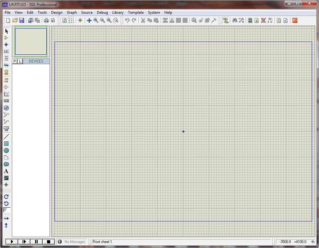
After installing Proteus , run ISIS Proteus Professional, will appear the following window interface :
Following is a brief description of each part of the function :
1. Schematic Editor window (The Editing Window): As the name implies , it is used to draw the schematic . Blue box as editable area, to put it inside the component . Note that this window is no scroll bar , you can use the preview window to change the schematic visual range .
2. Preview window (The Overview Window): It shows the two elements, one is this: When you are in the component list, select a component, it will show a preview of the element ; Another is that when you mouse focus falls on the principle diagram editor window ( ie, place the component into the schematic editor window Or after the Schematic Editor window, click the mouse ) , it will display the entire schematic diagram of the thumbnails, and will show a green box , green box which is the content of the current diagram window displays the contents of Therefore, you use the mouse to click on it to change the location of the green box , thereby changing the schematic visual range.
3. Model Selection Toolbar (Mode Selector Toolbar):
Main Modes:
1 * Select elements (components) ( selected by default )
2 * Place the connection point
3 * place a label ( the bus will be used )
4 * Place text
5 * for drawing bus
6 * for placing subcircuits
7 * for instant editing component parameters ( first click on the icon and then click the element you want to modify )
Tools:
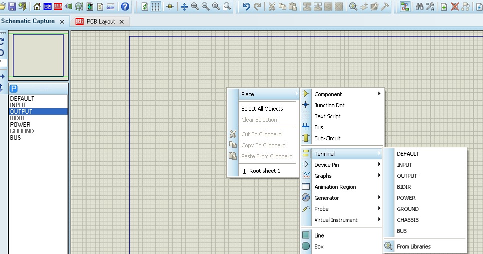
1 * terminal interface (terminals): There VCC, ground , output, input and other interfaces
2 * Device Pin : for drawing pin
3 * Emulation chart (graph): used for various analyzes, such as Noise Analysis
4 * recorder
5 * signal generator (generators)
6 * Voltage Probe: to be used when using simulation charts
7 * current probe : Using simulation to be used when using simulation charts
8 * Virtual Instrument : in the image above, an oscilloscope
2D graphics (2D Graphics):
1 * Drawing Lines
2 * draw a variety of boxes
3 * draw various circles
4 * draw a variety of arc
5 * draw various polygons
6 * draw various text
7 * draw symbols
8 * paintings origin , etc.
4 . Component List (The Object Selector):
For the selection of components (components), terminal interface (terminals), the signal generator (Generators), simulation chart (graph) and so on. For example , when you select ” Component (Components) “, click the ” P ” button will open the selected component dialog box, select an element after ( click on the ” OK ” after ) , the device will be displayed in the list of elements , later to use this element, just in the component list can be.
5 . Toolbars direction (Orientation Toolbar):
Rotate :
The rotation angle can be an integer multiple of 90 .
Flip:
Flip Horizontal and vertical flip finish . Use: Right-click the component , and then click ( left-click ) the corresponding rotation icon.
6 . Simulation Toolbar
1 * Run
2 * single-step operation
3 * Pause
4 * Stop
AVR microcontroller simulation example:
We want design an AVR driver for a LCD1602 and monitor it with an oscilloscope data lines. Parts of file formats generated by the compiler are different, such as ICC is COF, IAR is D90, GCC is COF, ELF. Proteus supports files COF, D90, HEX , etc.
Run Proteus Professional , the following window appears :
1, Add the components, in this case ATMEGA16, LM016L (LCD1602), after we’ ll add the oscilloscope.Click the “P” button to select Component dialog box appears
KEYWORDS of the dialog box , enter the ATMEGA16, get the following results :
>
Click OK, and close the dialog box , then the components listed in the list ATMEGA16, also find LM016L. The end result :
2 , place components: the component list, select Left ATMEGA16, in the schematic editor window, click the left button , so ATMEGA16 is placed in the Schematic Editor window . Similarly placed LM016L.
Add “ground” : Left Select model selection toolbar icon appears:
Left selection GROUND, and in the schematic editor window, left-click , so that the “ground” was placed into the Schematic Editor window .
Add Oscilloscope: Left Select model selection toolbar icon appears:
Left selection OSCILLOSCOPE, and in the schematic editor window left click , so that the oscilloscope is placed to the Schematic Editor window.
place components paying attention to place them inside the blue box of workarea.
3 . Connection. AVR, LCD ‘s VSS, VDD, VEE don’t need connections , the default VSS = 0V, VDD = 5V, VEE =-5V, GND = 0V
4 . Add a simulation file. Right click before on ATMEGA16 then select Edit Properties
in the Program File , click the File Browser dialog box, locate lcd_C.hex file, click OK to finish adding files.Set Clock Frequency at 8MHz, click OK to exit.
5 . Simulation
Click Start simulation :
Description: red for high, blue represents low, gray represents uncertainty level (floating). Running in the Debug menu, you can view the AVR related resources.
6 , the source code debugging
Proteus supports COF file debugging. Be sure to create this file in your compiler options.Complete the schematic drawing and add debug files (COF file ) , click:
the AVR Source Code window appears , if the state does not appear in the debugger , go to Debug menu to find .
Let’s say something about these icons
1 * continuous operation , it will exit the single-step debug state , and close the AVR Source Code window
2 * single-step operation , skip directly encountered Functions
3 * single-step operation , will enter its internal encountered Functions
4 * out of the current function , when using 3 * into the internal function , use it immediately on exiting the function returns a function , it should be seen in conjunction with the 3 *
5 * run to the line where the mouse
6 * Add or remove a breakpoint , the breakpoint is set using the program will stop at the breakpoint.
How to unhide hidden pins in proteus?
\$\begingroup\$
In order to see the hidden pins and the nets they are connected to you should double click the microcontroller and then click the hidden pins button.
There is no need to unhide the power pins, just connect the 5v regulator output to the Vcc net and the regulator ground to a GND net.
To place a Vcc terminal (the upwards pointing triangle) select the terminals menu, place a POWER terminal and double click it to select Vcc net. For the ground terminal just place a GROUND terminal, it’s already connected to the GND net.
Then when you open the ARES layout you will see the following connections from the regulator to the microcontroller power supply pins
Getting Started with Proteus
Thanks for this article to archeng504
After installing Proteus , run ISIS Proteus Professional, will appear the following window interface :
Following is a brief description of each part of the function :
1. Schematic Editor window (The Editing Window): As the name implies , it is used to draw the schematic . Blue box as editable area, to put it inside the component . Note that this window is no scroll bar , you can use the preview window to change the schematic visual range .
2. Preview window (The Overview Window): It shows the two elements, one is this: When you are in the component list, select a component, it will show a preview of the element ; Another is that when you mouse focus falls on the principle diagram editor window ( ie, place the component into the schematic editor window Or after the Schematic Editor window, click the mouse ) , it will display the entire schematic diagram of the thumbnails, and will show a green box , green box which is the content of the current diagram window displays the contents of Therefore, you use the mouse to click on it to change the location of the green box , thereby changing the schematic visual range.
3. Model Selection Toolbar (Mode Selector Toolbar):
Main Modes:
1 * Select elements (components) ( selected by default )
2 * Place the connection point
3 * place a label ( the bus will be used )
4 * Place text
5 * for drawing bus
6 * for placing subcircuits
7 * for instant editing component parameters ( first click on the icon and then click the element you want to modify )
Tools:
1 * terminal interface (terminals): There VCC, ground , output, input and other interfaces
2 * Device Pin : for drawing pin
3 * Emulation chart (graph): used for various analyzes, such as Noise Analysis
4 * recorder
5 * signal generator (generators)
6 * Voltage Probe: to be used when using simulation charts
7 * current probe : Using simulation to be used when using simulation charts
8 * Virtual Instrument : in the image above, an oscilloscope
2D graphics (2D Graphics):
1 * Drawing Lines
2 * draw a variety of boxes
3 * draw various circles
4 * draw a variety of arc
5 * draw various polygons
6 * draw various text
7 * draw symbols
8 * paintings origin , etc.
4 . Component List (The Object Selector):
For the selection of components (components), terminal interface (terminals), the signal generator (Generators), simulation chart (graph) and so on. For example , when you select ” Component (Components) “, click the ” P ” button will open the selected component dialog box, select an element after ( click on the ” OK ” after ) , the device will be displayed in the list of elements , later to use this element, just in the component list can be.
5 . Toolbars direction (Orientation Toolbar):
Rotate :
The rotation angle can be an integer multiple of 90 .
Flip:
Flip Horizontal and vertical flip finish . Use: Right-click the component , and then click ( left-click ) the corresponding rotation icon.
6 . Simulation Toolbar
1 * Run
2 * single-step operation
3 * Pause
4 * Stop
AVR microcontroller simulation example:
We want design an AVR driver for a LCD1602 and monitor it with an oscilloscope data lines. Parts of file formats generated by the compiler are different, such as ICC is COF, IAR is D90, GCC is COF, ELF. Proteus supports files COF, D90, HEX , etc.
Run Proteus Professional , the following window appears :
1, Add the components, in this case ATMEGA16, LM016L (LCD1602), after we’ ll add the oscilloscope.Click the “P” button to select Component dialog box appears
KEYWORDS of the dialog box , enter the ATMEGA16, get the following results :
>
Click OK, and close the dialog box , then the components listed in the list ATMEGA16, also find LM016L. The end result :
2 , place components: the component list, select Left ATMEGA16, in the schematic editor window, click the left button , so ATMEGA16 is placed in the Schematic Editor window . Similarly placed LM016L.
Add “ground” : Left Select model selection toolbar icon appears:
Left selection GROUND, and in the schematic editor window, left-click , so that the “ground” was placed into the Schematic Editor window .
Add Oscilloscope: Left Select model selection toolbar icon appears:
Left selection OSCILLOSCOPE, and in the schematic editor window left click , so that the oscilloscope is placed to the Schematic Editor window.
place components paying attention to place them inside the blue box of workarea.
3 . Connection. AVR, LCD ‘s VSS, VDD, VEE don’t need connections , the default VSS = 0V, VDD = 5V, VEE =-5V, GND = 0V
4 . Add a simulation file. Right click before on ATMEGA16 then select Edit Properties
in the Program File , click the File Browser dialog box, locate lcd_C.hex file, click OK to finish adding files.Set Clock Frequency at 8MHz, click OK to exit.
5 . Simulation
Click Start simulation :
Description: red for high, blue represents low, gray represents uncertainty level (floating). Running in the Debug menu, you can view the AVR related resources.
6 , the source code debugging
Proteus supports COF file debugging. Be sure to create this file in your compiler options.Complete the schematic drawing and add debug files (COF file ) , click:
the AVR Source Code window appears , if the state does not appear in the debugger , go to Debug menu to find .
Let’s say something about these icons
1 * continuous operation , it will exit the single-step debug state , and close the AVR Source Code window
2 * single-step operation , skip directly encountered Functions
3 * single-step operation , will enter its internal encountered Functions
4 * out of the current function , when using 3 * into the internal function , use it immediately on exiting the function returns a function , it should be seen in conjunction with the 3 *
5 * run to the line where the mouse
6 * Add or remove a breakpoint , the breakpoint is set using the program will stop at the breakpoint.
So you have finished reading the how to place ground in proteus topic article, if you find this article useful, please share it. Thank you very much. See more: Ground in proteus, Arduino in proteus, Power in Proteus, Vee in Proteus, Connector proteus, Volts proteus, Function generator proteus, Add Arduino to Proteus