
You are looking for information, articles, knowledge about the topic nail salons open on sunday near me 아두 이노 digitalread on Google, you do not find the information you need! Here are the best content compiled and compiled by the https://chewathai27.com/to team, along with other related topics such as: 아두 이노 digitalread 아두이노 digitalread 스위치, 아두이노 output, digitalRead, 아두이노 digitalwrite analogwrite, digitalRead HIGH, 아두이노 디지털 핀, 아두이노 핀 설명, 아두이노 디지털 핀 출력 전류
아두 이노 digitalread
- Article author: www.iamamaker.kr
- Reviews from users: 20805
 Ratings
 - Top rated: 4.3
- Lowest rated: 1
- Summary of article content: Articles about 아두 이노 digitalread digitalRead() 함수는 아두이노의 디지털 핀으로부터 HIGH 또는 LOW 값을 읽어옵니다. 핀이 어떠한 회로에도 연결되어 있지 않으면 HIGH 또는 LOW 중 … …
- Most searched keywords: Whether you are looking for 아두 이노 digitalread digitalRead() 함수는 아두이노의 디지털 핀으로부터 HIGH 또는 LOW 값을 읽어옵니다. 핀이 어떠한 회로에도 연결되어 있지 않으면 HIGH 또는 LOW 중 …
- Table of Contents:
[아두이노 함수] digitalRead() 함수 : 네이버 블로그
- Article author: m.blog.naver.com
- Reviews from users: 317 Ratings
- Top rated: 3.2
- Lowest rated: 1
- Summary of article content: Articles about [아두이노 함수] digitalRead() 함수 : 네이버 블로그 [아두이노 함수] digitalRead() 함수 … 안녕하세요, 강남 대치동 1등 코딩학원! 어린이 청소년 전문 자율참여형 코딩학원. 잼있고 깊게, 비교할수록 잼 … …
- Most searched keywords: Whether you are looking for [아두이노 함수] digitalRead() 함수 : 네이버 블로그 [아두이노 함수] digitalRead() 함수 … 안녕하세요, 강남 대치동 1등 코딩학원! 어린이 청소년 전문 자율참여형 코딩학원. 잼있고 깊게, 비교할수록 잼 …
- Table of Contents:
카테고리 이동
코딩학원 잼코딩학원
이 블로그
아두이노 관련 지식
카테고리 글
카테고리
이 블로그
아두이노 관련 지식
카테고리 글
![[아두이노 함수] digitalRead() 함수 : 네이버 블로그](https://blogthumb.pstatic.net/20160924_130/jamduino_1474710265130NyBb3_JPEG/led13.jpg?type=w2)
아두이노 기초 강좌 5 – digitalRead, digitalWrite | Hard Copy World
- Article author: www.hardcopyworld.com
- Reviews from users: 10320 Ratings
- Top rated: 3.1
- Lowest rated: 1
- Summary of article content: Articles about 아두이노 기초 강좌 5 – digitalRead, digitalWrite | Hard Copy World digitalRead 함수는 이름처럼 on/off 상태를 확인할 수 있게 해주는 함수죠. 이 함수는 핀 번호값을 전달하면 해당 핀이 on인지 off 인지 결과를 출력 … …
- Most searched keywords: Whether you are looking for 아두이노 기초 강좌 5 – digitalRead, digitalWrite | Hard Copy World digitalRead 함수는 이름처럼 on/off 상태를 확인할 수 있게 해주는 함수죠. 이 함수는 핀 번호값을 전달하면 해당 핀이 on인지 off 인지 결과를 출력 … 아두이노 기초 강좌는 아두이노를 처음 접하시는 전자분야 비 전공자를 위한 강좌입니다. 이해를 위해서는 간단한 프로그래밍 지식이 필요할 수 있습니다. 프로그래밍이 처음이라면 [아두이노 프로그래밍 기초] 강좌를 먼저 읽으시길 권해 드립니다. 프로그래밍 기초 강좌 전체보기
- Table of Contents:

이티의 IT :: 아두이노 디지털 입력, digitalRead () 사용하기
- Article author: by-man.tistory.com
- Reviews from users: 9216 Ratings
- Top rated: 4.2
- Lowest rated: 1
- Summary of article content: Articles about 이티의 IT :: 아두이노 디지털 입력, digitalRead () 사용하기 지정된 디지털 핀에서 HIGH또는 값을 읽습니다 LOW. 사용 예. digitalRead(pin);. 매개 변수. pin: 읽고 싶은 Arduino 핀 번호. …
- Most searched keywords: Whether you are looking for 이티의 IT :: 아두이노 디지털 입력, digitalRead () 사용하기 지정된 디지털 핀에서 HIGH또는 값을 읽습니다 LOW. 사용 예. digitalRead(pin);. 매개 변수. pin: 읽고 싶은 Arduino 핀 번호. 오늘은 아두이노의 디지털핀에 들어온 데이터를 읽는 disgtalRead() 함수에 대해 알아보도록 하겠습니다. disgtalRead() 정의 지정된 디지털 핀에서 HIGH또는 값을 읽습니다 LOW. 사용 예 digitalRead(pin); 매..Everything iT, 외계인의 눈으로 세상을 바라보는
- Table of Contents:
digitalRead() | 아두이노 참조
- Article author: arduinogetstarted.com
- Reviews from users: 787 Ratings
- Top rated: 4.2
- Lowest rated: 1
- Summary of article content: Articles about digitalRead() | 아두이노 참조 지정한 디지털 핀에서 값(HIGH 또는 LOW)을 읽습니다. 문법. digitalRead(pin). 매개변수. …
- Most searched keywords: Whether you are looking for digitalRead() | 아두이노 참조 지정한 디지털 핀에서 값(HIGH 또는 LOW)을 읽습니다. 문법. digitalRead(pin). 매개변수. digitalRead() 함수 지정한 디지털 핀에서 값(`HIGH` 또는 `LOW`)을 읽습니다digitalRead(),Arduino digitalRead(),digitalRead() Arduino,digitalRead,Arduino digitalRead,digitalRead Arduino,digitalRead() 아두이노 참조
- Table of Contents:
설명
문법
매개변수
반환값
예제 코드
더보기
ARDUnity Project: 아두이노 프로그래밍 기초
- Article author: ardunityproject.blogspot.com
- Reviews from users: 24312 Ratings
- Top rated: 3.9
- Lowest rated: 1
- Summary of article content: Articles about ARDUnity Project: 아두이노 프로그래밍 기초 아두이노 프로그래밍에 있어서 기초는 다음의 함수 역할을 이해하는 것입니다. setup; loop; pinMode; digitalWrite; digitalRead; analogWrite … …
- Most searched keywords: Whether you are looking for ARDUnity Project: 아두이노 프로그래밍 기초 아두이노 프로그래밍에 있어서 기초는 다음의 함수 역할을 이해하는 것입니다. setup; loop; pinMode; digitalWrite; digitalRead; analogWrite …
- Table of Contents:
페이지
2016년 7월 1일 금요일
프로필
이 블로그 검색
블로그 보관함
카테고리

[아두이노 강좌] 12. 아두이노 디지털핀 신호 입력받기 / pinMode(), digitalRead() > 아두이노 | 메이크쉐어
- Article author: makeshare.org
- Reviews from users: 32668 Ratings
- Top rated: 3.1
- Lowest rated: 1
- Summary of article content: Articles about [아두이노 강좌] 12. 아두이노 디지털핀 신호 입력받기 / pinMode(), digitalRead() > 아두이노 | 메이크쉐어 디지털 신호 아두이노디지털 핀에 대한 개념은 이전 강좌 11번을 참고 … if (digitalRead(BUTTON) == HIGH) { // 만약 2번핀에 HIGH가 입력된다면. …
- Most searched keywords: Whether you are looking for [아두이노 강좌] 12. 아두이노 디지털핀 신호 입력받기 / pinMode(), digitalRead() > 아두이노 | 메이크쉐어 디지털 신호 아두이노디지털 핀에 대한 개념은 이전 강좌 11번을 참고 … if (digitalRead(BUTTON) == HIGH) { // 만약 2번핀에 HIGH가 입력된다면. 아두이노 개요 아두이노의 디지털 핀으로 디지털 신호를 입력받아 보도록 합시다! 디지털 신호 아두이노디지털 핀에 대한 개념은 이전 강좌 11번을 참고해주세요. 스위치로 LED 제어하기 이전 강좌11에서는 디지털신호를 출력하여 LED의 전원을 제어해봤습니다. 입력도 별반다르지 않습니다. 외부에서 아두이노로 HIGH신호 LOW신호를 보내면 그게 바로&nbs…
- Table of Contents:
최신글
최신댓글
![[아두이노 강좌] 12. 아두이노 디지털핀 신호 입력받기 / pinMode(), digitalRead() > 아두이노 | 메이크쉐어” style=”width:100%”><figcaption>[아두이노 강좌] 12. 아두이노 디지털핀 신호 입력받기 / pinMode(), digitalRead() > 아두이노 | 메이크쉐어</figcaption></figure>
<p style=](https://makeshare.org/data/editor/1605/2dc6cb7277117a02103aaa55ec030085_1462621938_65.jpg) Read More
Read More
Digital Read in Arduino
- Article author: linuxhint.com
- Reviews from users: 1990 Ratings
- Top rated: 4.2
- Lowest rated: 1
- Summary of article content: Articles about Digital Read in Arduino In Arduino, a built-in function is used for reading the digital inputs. This function of digitalRead() is used and the digital input from the digital pins … …
- Most searched keywords: Whether you are looking for Digital Read in Arduino In Arduino, a built-in function is used for reading the digital inputs. This function of digitalRead() is used and the digital input from the digital pins … The digital read serial is the process by which we can read the input signals from the digital input pins of Arduino and the digital read can be done by using the built-in function of digitalRead(). In this write-up, the digital read serial is explained with the help of an example and the digital signals through digital pins have only two possible outcomes, either low or high.
- Table of Contents:
digitalRead() function in Arduino
Example digitalRead() function in Arduino
Conclusion
See more articles in the same category here: https://chewathai27.com/to/blog.
아두이노 기초 강좌 5 – digitalRead, digitalWrite
아두이노 기초 강좌는 아두이노를 처음 접하시는 전자분야 비 전공자를 위한 강좌입니다. 이해를 위해서는 간단한 프로그래밍 지식이 필요할 수 있습니다. 프로그래밍이 처음이라면 [아두이노 프로그래밍 기초] 강좌를 먼저 읽으시길 권해 드립니다.
=============================================================
.
아두이노의 기본 구조를 익혔다면 이제 아두이노에 수십개 달린 핀(pin)들을 어떻게 사용하는지에 대해서 알아볼 차례입니다. 이번 회에서 실험해 볼 대상 핀은 아두이노에 D2 ~ D13으로 프린트 되어 있는 디지털 핀들입니다. 아두이노에서는 이 디지털 핀들에 들어오는 전압(0V~5V)을 읽을 수도 있고, 이 핀으로 전압을 출력할 수도 있습니다. 이런 동작을 하기위해 사용되는 함수가 digitalRead, digitalWrite 함수입니다. 이름처럼 on(=5V, HIGH), off(=0V, LOW) 두 가지 상태를 읽고 쓸수 있는 함수입니다. 예제를 통해 어떻게 동작하는지 보시죠.
1. 버튼 예제
이번 장에서는 버튼을 눌렀을 때 이를 감지하고 그 결과를 Serial Monitor로 출력하는 예제를 보도록 하겠습니다. 아두이노 공식 홈페이지에도 소스와 매뉴얼이 있으니 참고하시면 됩니다.
http://arduino.cc/en/Tutorial/DigitalReadSerial
아두이노 회로를 위와 같이 구성해서 테스트 할 수 있습니다.
버튼 아래쪽에 달려 있는건 10k Ohm 저항입니다. 5V – GND 즉 +, – 가 아무런 중간 장치 없이 직접 연결되지 않도록 달아둔거라 생각하심 됩니다. 버튼 아래쪽 면에 있는 다리 2개를 5V, GND(그라운드) 로 연결해 두고, 위쪽 면에 있는 다리를 2번 핀에 연결해 뒀습니다. 버튼은 한쪽면에 있는 다리끼리는 연결되어 있고, 서로 다른면의 다리는 버튼을 눌러야만 연결됩니다. 그래서… 버튼이 눌려지지 않은 상태에서는 2번 핀에 아무것도 연결이 안되므로 2번 핀의 입력을 읽었을 때 off 상태(0, 0V, LOW) 로 읽히고, 버튼을 누르면 5v 전류가 2번 핀으로 연결되므로 on 상태로(1, 5V, HIGH) 읽힙니다.
2. digitalRead 예제 소스
어떻게 동작되는지 대강의 흐름을 파악했으니 이걸 구동하는 예제 소스를 보시겠습니다. 아두이노 기본 예제 중 하나인 DigitalReadSerial 예제입니다.
/* DigitalReadSerial Reads a digital input on pin 2, prints the result to the serial monitor This example code is in the public domain. */ // digital pin 2 has a pushbutton attached to it. Give it a name: int pushButton = 2; // the setup routine runs once when you press reset: void setup() { // initialize serial communication at 9600 bits per second: Serial.begin(9600); // make the pushbutton’s pin an input: pinMode(pushButton, INPUT); } // the loop routine runs over and over again forever: void loop() { // read the input pin: int buttonState = digitalRead(pushButton); // print out the state of the button: Serial.println(buttonState); delay(1); // delay in between reads for stability }
말씀드렸다시피 2번 핀(D2)을 통해서 버튼이 눌러졌는지 확인할 겁니다. 그래서 pushButton 변수에 2를 넣어뒀습니다.
이제 초기화를 담당하는 setup() 함수를 보시죠. 초기화 할 때 해야할 작업은 2가지입니다. Serial 통신을 통해 PC로 현재 상태를 보내줘야 하기 때문에 이 기능을 담당하는 Serial 클래스를 초기화 해야 합니다. 보통 기본 9600 속도로 초기화 하며 아래와 같이 사용합니다. PC에서 실행하는 아두이노 Serial Monitor도 같은 속도로 설정되어야 합니다.
Serial.begin(9600);
begin 함수가 Serial 통신을 초기화 하기 위해 Serial 클래스 안에 정의되어 있는 함수입니다. 이걸 호출하면 Serial 통신을 통해 PC와 통신할 준비는 끝납니다.
앞서서 디지털 핀은 on, off 상태를 읽을수도 쓸수도 있다고 했습니다. 그래서 어떤 모드로 사용할 것인지를 미리 지정해 줘야 합니다. 아래와 같이 pinMode 함수를 이용해서 설정할 수 있습니다.
pinMode(pushButton, INPUT);
pushButton으로 지정된 2번 핀을 INPUT(읽기) 모드로 사용하겠다는 뜻입니다. 출력 모드로 사용하고 싶다면 OUTPUT을 대신 넣으면 되겠죠.
이제 계속 반복해서 실행되는 loop 함수를 보시죠. 여기서는 버튼 상태를 읽고 그 값을 PC로 전송해 주는 작업을 해야겠습니다.
int buttonState = digitalRead(pushButton);
위 라인이 버튼의 상태를 읽는 라인입니다.
digitalRead 함수는 이름처럼 on/off 상태를 확인할 수 있게 해주는 함수죠. 이 함수는 핀 번호값을 전달하면 해당 핀이 on인지 off 인지 결과를 출력해줍니다. 위 코드에서는 digitalRead 가 출력하는 on/off 결과를 다시 buttonState라는 변수에 저장을 합니다.
digitalRead가 출력하는 결과는 정수로 전달하도록 정해져있어서, 이 값을 받아서 저장하는 buttonState라는 변수를 정수형(int)으로 만들었습니다. 실제로 digitalRead 함수는 지정한 핀의 상태가 off 상태일 때(입력되는 전압이 0V 일 때) 0을 전달하고, on 상태일 때(입력되는 전압이 5V) 일 때 1을 전달해줍니다. 0과 1로 표현하면 헷갈릴 우려가 있어서 아두이노에서는 이걸 LOW(0), HIGH(1) 라고 상수로 정의해 뒀습니다.
자 이제 buttonState 라는 변수에 저장된 0과 1값을 (LOW, HIGH) PC에 전달해줄 차례입니다.
Serial.println(buttonState);
Serial 클래스에는 println 이라는 함수가 미리 정의되어 있습니다. Serial.println(출력할 값) 형태로 호출하면 PC로 전송해줍니다. 0 또는 1이 전송되겠네요.
delay(1); // delay in between reads for stability
위와 같이 마지막에 delay 함수가 사용되었습니다. 주석에 적혀있다시피 굉장히 빠른 속도로 loop 안에 정의된 작업이 반복되기 때문에 안정성을 위해 잠시 아두이노가 멈추도록 하는겁니다. 1 이라고 적은 것은 1/1000 초 동안 쉬도록 하기 위해서입니다. 아두이노는 오로지 하나의 thread(쓰레드, 작업하는 사람) 만을 사용하기 때문에 delay 함수로 멈추게되면 정해진 시간동안 다른 어떤 작업도 할 수가 없습니다. 그럼에도 delay 는 매우 흔하게 사용되는 유용한 함수입니다.
이제 소스코드 컴파일 – 업로드를 마치고 아두이노 개발환경에서 Serial Monitor 창을 켜보시죠. 그러면 [0000000000000000000] 이 빠르게 출력될 겁니다. 스위치를 누르면 [000000011000000] 이렇게 1(HIGH)이 누른 시간만큼 출력될 겁니다.
3. digitalWrite 예제 소스
아두이노 디지털 핀을 읽는 방법을 알아봤으니 이제 쓰는 방법을 알아보겠습니다. 기억하시겠지만 아두이노 13번 핀은 아두이노가 자체적으로 가진 LED가 연결되어 있습니다. 이제 버튼을 누르면 PC에서 확인하는 대신 아두이노의 LED를 통해 불빛으로 보여주도록 수정해 보겠습니다. 아두이노가 가진 LED를 이용할 예정이니 위에서 설정한 회로를 그대로 이용하시면 됩니다.
/* DigitalReadSerial Reads a digital input on pin 2, prints the result to the LED This example code is in the public domain. */ // digital pin 2 has a pushbutton attached to it. Give it a name: int pushButton = 2; // LED on Arduino int led = 13; // the setup routine runs once when you press reset: void setup() { // make the pushbutton’s pin an input: pinMode(pushButton, INPUT); // set led pin as output: pinMode(led, OUTPUT); } // the loop routine runs over and over again forever: void loop() { // read the input pin: int buttonState = digitalRead(pushButton); // print out the state of the button: digitalWrite(led, buttonState); delay(1); // delay in between reads for stability }
바뀐 부분만 이해를 하시면 되겠습니다. 먼저 이전 예제에서 사용했던 Serial 클래스의 함수들이 모두 빠졌습니다. PC가 아니라 LED로 알려줄려고 하니까요. 대신 led 핀 번호를저장하는 변수가 사용되었습니다.
int led = 13;
setup 함수를 보시죠. 디지털 13번 핀을 통해 LED를 on, off 제어할 예정입니다. 13번 핀의 출력을 상황에 따라 0V, 5v로 바꿔야겠죠. 따라서 pin mode 를 OUTPUT으로 초기화를 해줘야 합니다.
// set led pin as output: pinMode(led, OUTPUT);
이제 기존에 PC로 출력하던 코드를 LED로 출력하도록 바꾸면 됩니다. Serial.println 으로 출력하던 부분을 digitalWrite 함수로 교체하면 됩니다.
// print out the state of the button: digitalWrite(led, buttonState);
digitalWrite 함수는 핀 번호에 해당하는 핀을 on, off 상태(0V, 5V) 로 바꿔주는 함수입니다. 앞서 digitalRead 함수를 통해 버튼 상태를 읽어서 buttonState 변수에 저장했습니다. 그럼 buttonState 변수에는 on(=HIGH, 5V), off(=LOW, 0V) 값이 저장되어 있습니다. 이걸 그대로 digitalWrite 함수에 사용하면… 버튼 상태가 누름(=HIGH, 5V) 일 때 그대로 입력값으로 사용되므로 LED가 켜지게 됩니다. 뗀 상태일 때는 반대로 될거구요. 위 라인을 굳이 복잡하게 바꾸면…
if(buttonState == HIGH) { digitalWrite(led, HIGH); } else { digitalWrite(led, LOW); }
이렇게 됩니다.
이제 직접 테스트를 해보시면. 버튼의 입력 상태를 LED로 확인하실 수 있으실겁니다!!
# 강좌의 내용이 명확하지 않거나 이해가 힘든 부분이 있으시면 댓글로 말씀해 주세요. 해당 부분을 지속적으로 업데이트 하겠습니다.
=============================================================
이 문서는 작성자의 동의없이 개인적인 목적 외의 상업적인 목적으로 활용되어서는 안됩니다.
이 문서의 일부 혹은 전체를 수정, 삭제, 재배포 하여서는 안됩니다.
작성자 : GodsTale ([email protected])
[아두이노 강좌] 12. 아두이노 디지털핀 신호 입력받기 / pinMode(), digitalRead()
개요
아두이노의 디지털 핀으로 디지털 신호를 입력받아 보도록 합시다! 디지털 신호, 아두이노
디지털 핀에 대한 개념은 이전 강좌 11번을 참고해주세요.
스위치로 LED 제어하기
이전 강좌11에서는 디지털신호를 출력하여 LED의 전원을 제어해봤습니다. 입력도 별반
다르지 않습니다. 외부에서 아두이노로 HIGH신호, LOW신호를 보내면 그게 바로 아두
이노가 디지털 신호를 입력받는겁니다. 그림으로 살펴볼까요?
그림1. 디지털 신호 입력
(외부기기라고 표현했지만 아두이노가 아두이노로 신호를 보낼 수도 있어요.. ^^)
위 사진과 같이 외부에서 아두이노 디지털 핀으로 3~5V를 보내는 경우 아두이노에 디지털
신호 HIGH가 입력됬다고 표현하며, 0~1.5V가 입력된 경우 LOW가 입력됬다고 표현합니다.
본격적인 실습에 앞서 스위치 부품에 대해 간단하게 알아보도록 합시다.
스위치(Switch)란?
스위치는 전기의 흐름을 잇거나 끊기 위한 제어장치입니다. 조명이나 컴퓨터 등을 끄거나
킬 때 누르는 버튼도 일종의 스위치입니다. 본 예제에서 사용되는 스위치는 푸시 버튼으로,
상단의 버튼 부분과 하단의 다리 4개로 구성되어 있습니다.
그림2. 푸시버튼 내부 회로도
버튼을 누르지 않을 경우, 1번과 2번 // 3번과 4번 다리가 서로 연결되어 있으며 버튼을
누를 경우, 4개의 다리가 모두 연결되어 전기가 통하게 됩니다.
준비물
회로도 연결
LED를 디지털 핀 8번과 GND에 연결해주도록 합니다. (중간에 220옴 저항)
푸시버튼을 5V, GND, 디지털 2번핀에 연결해주도록 합니다. (10K저항 사용)
회로에 대해 간단하게 설명해보도록 하겠습니다.
① LED는 디지털 8번핀에서 HIGH를 출력하느냐, LOW를 출력하느냐에 따라 전원이
ON되거나 OFF됩니다.
② 회로를 보면 아두이노 5V 출력핀 – 버튼 스위치 – 디지털2번핀 으로 연결되어있습니다.
버튼을 누를 경우 디지털 2번핀에 5V(HIGH신호)가 입력되겠죠?
③ 우리가 만들 프로그램의 내용은 이렇습니다. 버튼을 눌러 디지털 핀 2번에 HIGH신호가
입력되면 디지털 8번핀에 HIGH 신호를 보내고, 버튼을 누르지 않아 디지털 2번핀에 LOW
신호가 입력될 경우 디지털 8번핀에 LOW 신호를 보낸다. 그럼 바로 GOGO!
프로그램 코드 (2)
int LED = 8; // LED라는 변수를 만들고 8을 저장한다.
int BUTTON = 2; // LED라는 변수를 만들고 2를 저장한다.
void setup() {
pinMode(BUTTON, INPUT); // BUTTON(디지털 2번)핀을 입력모드로
pinMode(LED, OUTPUT); // LED(디지털 8번)핀을 출력모드로
}
void loop() {
if (digitalRead(BUTTON) == HIGH) { // 만약 2번핀에 HIGH가 입력된다면
digitalWrite(LED, HIGH); // 8번핀에 HIGH 신호를 출력하고,
}
else { // 그게 아니라면(2번핀에 HIGH가 입력되지 않는다면)
digitalWrite(LED, LOW); // 8번핀에 LOW 신호를 출력한다.
}
}
뭔가 새로 추가된게 굉장히 많아 보여요.. 하지만 별거 없습니다. 코드를 해석해봅시다.
프로그램 해석
맨위에서 변수라는 저장공간을 만들고 그안에 대입할 수를 저장합니다. 즉 LED라는 공간에
8을 저장함으로써 LED를 8로 사용할 수 있습니다. 변수에 대한 내용은 여기를 클릭해서
더 자세하게 공부해보세요.
버튼(2번핀)을 입력모드로, LED(8번핀)을 출력모드로 설정한 후, 버튼에 HIGH신호가
입력되면 LED에 HIGH신호를 출력하여 LED를 켜고, 버튼에 LOW 신호가 입력되면 LED에
LOW신호를 출력하여 LED를 끕니다.
사용된 함수 정리하기
■digitalRead(핀번호)
설정 핀에 디지털 신호를 입력받기 위한 함수입니다.
매개변수
핀번호 – 신호를 입력받을 디지털 핀 번호를 적어줍니다.
■if(조건문)
‘만약에 ~라면’ 이라는 조건문을 만들 수 있습니다.
매개변수
조건문 – 해당되는 ‘조건문’을 적어줍니다.
강좌를 마무리 하기전에 회로도를 다시 한번 살펴봅시다. 회로를 살펴보면 10K 저항이
연결된 것을 확인할 수 있습니다. 이 저항은 무슨 용도로 사용된 것일까요?
바로 플롯현상 때문입니다. 쉽게 말해, 회로에서 저항을 제거하면 아두이노에서 나오는 5V의
전기가 디지털 2번핀으로 들어가지 않고 길을 해매어 이도저도 아닌 상태가 됩니다. 전류는
저항이 낮은 쪽으로 흐르는 성질이 있기 때문에 이를 이용하여 플롯현상을 해결해준 것입니다.
자세한 내용(플롯현상, 풀 업 저항회로, 풀 다운 저항 회로)은 여기를 클릭하여 확인해보세요. ^^
Digital Read in Arduino
To read the digital input from the user, we used the approach of digital read serial. For example, we have to take the input of a digital stopwatch in a binary number; zero and one. This input can be read by the digital pins of Arduino, and can utilize the results in some other task.
First, understand what is the digital input? The input values have only two possible states: either LOW (0 volts) or HIGH(5 volts) are known as the digital inputs. In this write-up, the digital read serial in Arduino is explained with the help of an example.
digitalRead() function in Arduino
In Arduino, a built-in function is used for reading the digital inputs. This function of digitalRead() is used and the digital input from the digital pins of Arduino are taken. It reads the input either in High or Low state, moreover, the analog pins can also be used as digital pins in Arduino.
Example : digitalRead() function in Arduino
We will take an example of a push button so that when we press the push button, its state will become high and when we release it, its state will be Low. Consider the following code for this example:
int pButton = 2 ;
void setup ( ) {
Serial.begin ( 9600 ) ;
pinMode ( pButton,INPUT ) ;
}
void loop ( ) {
int bState =digitalRead ( pButton ) ;
Serial.println ( bState ) ;
delay ( 5000 ) ;
}
Explanation: An integer variable “pbutton” is declared with the value of 2 so the push button can be connected to pin 2 and using the pinMode() function we declared the behavior of pin 2 as an input. Then we initialize another integer variable with the name of “bState” and store the states of the push button in it. Finally, we print the result of bState on the serial monitor and serial plotter through serial communication. This process will be repeated again and again for an infinite time period after the delay of 5 seconds (5000 milliseconds) because this code is executed in a loop section.
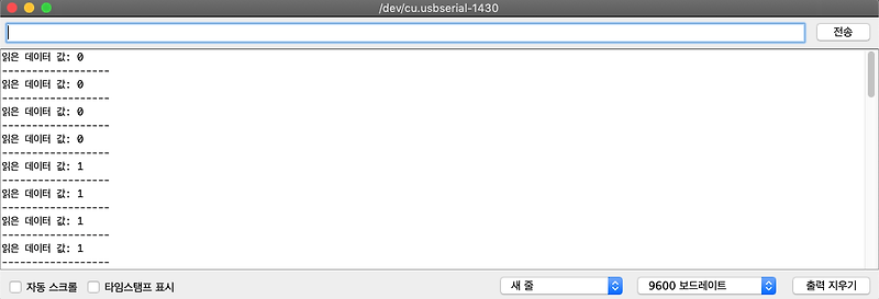
The serial monitor output will be like this:
And the serial plotter output will be like this:
The push-button was pressed, the Arduino read the input High and then the push button was released so it read the input low. Again the push button is pressed and then released so the next output becomes high and then low.
For its hardware configuration, we need the following components:]
Resistor (1kΩ)
Arduino Uno
Jumper wires
Push-button
The following is the circuit diagram of the circuit:
Connect one end of the resistor to the ground and the other terminal to the push button. Connect pin 2 with the same terminal of the push button which is connected with a resistor and the other terminal with the 5-volt power source. So when the push button is pressed, pin 2 receives a high signal and when the button is released, a low signal of 0 volts will be read by pin 2.
The hardware configuration is:
Conclusion
The digital read serial is the process by which we can read the input signals from the digital input pins of Arduino and the digital read serial can be done by using the built-in function of digitalRead(). In this write-up, the digital read serial is explained with the help of an example and the digital signals through digital pins have only two possible outcomes, either low or high.
So you have finished reading the 아두 이노 digitalread topic article, if you find this article useful, please share it. Thank you very much. See more: 아두이노 digitalread 스위치, 아두이노 output, digitalRead, 아두이노 digitalwrite analogwrite, digitalRead HIGH, 아두이노 디지털 핀, 아두이노 핀 설명, 아두이노 디지털 핀 출력 전류