
You are looking for information, articles, knowledge about the topic nail salons open on sunday near me 아두 이노 rgb led on Google, you do not find the information you need! Here are the best content compiled and compiled by the https://chewathai27.com/to team, along with other related topics such as: 아두 이노 rgb led 아두이노 rgb led 모듈, 아두이노 rgb led 여러개, rgb led바, led 아두이노, Arduino RGB LED, 아두이노 led 제어, RGB LED datasheet, 아두이노 3색 LED PWM
Table of Contents
Arduino RGB LED Tutorial – Arduino Project Hub
- Article author: create.arduino.cc
- Reviews from users: 49547
 Ratings
 - Top rated: 3.2
- Lowest rated: 1
- Summary of article content: Articles about Arduino RGB LED Tutorial – Arduino Project Hub The RGB led consists of three different led’s, from the name you can guess that these led’s are red, green and blue. We can obtain many other … …
- Most searched keywords: Whether you are looking for Arduino RGB LED Tutorial – Arduino Project Hub The RGB led consists of three different led’s, from the name you can guess that these led’s are red, green and blue. We can obtain many other … You will learn how to use the RGB LED with Arduino to obtain different colors.blinky lights,led,lights,rgb
- Table of Contents:
Components and supplies
Apps and online services
About this project
Code
Schematics
Comments
[아두이노 강좌] 03. RGB LED 색깔 변경하기 – 가치창조기술 위키
- Article author: wiki.vctec.co.kr
- Reviews from users: 26527 Ratings
- Top rated: 4.5
- Lowest rated: 1
- Summary of article content: Articles about [아두이노 강좌] 03. RGB LED 색깔 변경하기 – 가치창조기술 위키 빛은 물감과 다르게 빨강, 초록, 파랑 빛을 섞으면 하얀색이 됩니다. 세개의 LED의 밝기를 동일하게 설정하면 전체적인 컬러는 하얀색이되며 파랑LED를 끄고, 빨강과 초록 … …
- Most searched keywords: Whether you are looking for [아두이노 강좌] 03. RGB LED 색깔 변경하기 – 가치창조기술 위키 빛은 물감과 다르게 빨강, 초록, 파랑 빛을 섞으면 하얀색이 됩니다. 세개의 LED의 밝기를 동일하게 설정하면 전체적인 컬러는 하얀색이되며 파랑LED를 끄고, 빨강과 초록 …
- Table of Contents:
![[아두이노 강좌] 03. RGB LED 색깔 변경하기 - 가치창조기술 위키](https://vctec.co.kr/web/wiki/arduino/tutorial/rgbled/project_3_on_breadboard.jpg)
아두 이노 rgb led
- Article author: kocoafab.cc
- Reviews from users: 17162 Ratings
- Top rated: 4.3
- Lowest rated: 1
- Summary of article content: Articles about 아두 이노 rgb led 참고로 현재버전의 아두이노 IDE는 한글입력 어려워, 한글 입력을 권장하지 않습니다. RGB LED를 활용한 프로젝트. 아크릴 램프. RGB LED를 활용하면 내가 … …
- Most searched keywords: Whether you are looking for 아두 이노 rgb led 참고로 현재버전의 아두이노 IDE는 한글입력 어려워, 한글 입력을 권장하지 않습니다. RGB LED를 활용한 프로젝트. 아크릴 램프. RGB LED를 활용하면 내가 …
- Table of Contents:
[아두이노] RGB(3색) LED 사용하기
- Article author: studyingandsuccess.tistory.com
- Reviews from users: 3624 Ratings
- Top rated: 4.9
- Lowest rated: 1
- Summary of article content: Articles about [아두이노] RGB(3색) LED 사용하기 [아두이노] RGB(3색) LED 사용하기 … LED 중에는 3가지 색을 낼 수 있는 제품이 있습니다. 다리가 4개이기 때문에 ‘4 leg LED’, ‘4 pin LED’, 또는 낼 수 … …
- Most searched keywords: Whether you are looking for [아두이노] RGB(3색) LED 사용하기 [아두이노] RGB(3색) LED 사용하기 … LED 중에는 3가지 색을 낼 수 있는 제품이 있습니다. 다리가 4개이기 때문에 ‘4 leg LED’, ‘4 pin LED’, 또는 낼 수 … LED 중에는 3가지 색을 낼 수 있는 제품이 있습니다. 다리가 4개이기 때문에 ‘4 leg LED’, ‘4 pin LED’, 또는 낼 수 있는 색깔이 빨강(Red), 초록(Green), 파랑(Blue)이라 ‘RGB LED’라고도 부릅니다. <그림 1>..
- Table of Contents:
티스토리 뷰
Common Cathode
Common Anode
![[아두이노] RGB(3색) LED 사용하기](https://img1.daumcdn.net/thumb/R800x0/?scode=mtistory2&fname=https%3A%2F%2Ft1.daumcdn.net%2Fcfile%2Ftistory%2F99CD5F355C3AA95117)
아두이노 강좌 #45 RGB LED 기초 사용법 기초 및 Orange, Yellow 컬러 표시 팁::Blacklog
- Article author: juahnpop.tistory.com
- Reviews from users: 25379 Ratings
- Top rated: 4.1
- Lowest rated: 1
- Summary of article content: Articles about 아두이노 강좌 #45 RGB LED 기초 사용법 기초 및 Orange, Yellow 컬러 표시 팁::Blacklog Arduino Uno RGB LED Basic 이번 포스트에서는 RGB LED 기초 사용법에 대해 설명 합니다. RGB LED로 여러가지 색을 표현하기 위해 사용되는 PWM 출력 방법에 대한 기초 … …
- Most searched keywords: Whether you are looking for 아두이노 강좌 #45 RGB LED 기초 사용법 기초 및 Orange, Yellow 컬러 표시 팁::Blacklog Arduino Uno RGB LED Basic 이번 포스트에서는 RGB LED 기초 사용법에 대해 설명 합니다. RGB LED로 여러가지 색을 표현하기 위해 사용되는 PWM 출력 방법에 대한 기초 … Arduino Uno RGB LED Basic 이번 포스트에서는 RGB LED 기초 사용법에 대해 설명 합니다. RGB LED로 여러가지 색을 표현하기 위해 사용되는 PWM 출력 방법에 대한 기초 적인 내용은 하단의 관련 포스트를 참고해..Hardware, Software, Productivity, DIY Project, Tip&Trics
- Table of Contents:
RGB LED 기초 사용법에 대해 설명
RGB LED를 사용하는 기초적인 방법으로 LED를 ONOFF하는 방식과 PWM을 사용하는 방식의 코드를 소개
티스토리툴바
틴커캐드 아두이노 3색 RGB LED 제어하기
- Article author: iot-lab.tistory.com
- Reviews from users: 23118 Ratings
- Top rated: 4.4
- Lowest rated: 1
- Summary of article content: Articles about 틴커캐드 아두이노 3색 RGB LED 제어하기 한쪽 방향으로 전류가 흐르도록 하는 반도체 소자를 다이오드라고 합니다. … 3색 LED는 빨강, 초록, 파랑의 3가지 색을 하나의 LED로 합친 것입니다. RGB … …
- Most searched keywords: Whether you are looking for 틴커캐드 아두이노 3색 RGB LED 제어하기 한쪽 방향으로 전류가 흐르도록 하는 반도체 소자를 다이오드라고 합니다. … 3색 LED는 빨강, 초록, 파랑의 3가지 색을 하나의 LED로 합친 것입니다. RGB … 이전 블로그에서 브레드보드와 LED 페이드 인/페이드 아웃 (PWM) 제어하는 방법을 알아보았습니다. https://iot-lab.tistory.com/175 틴커캐드 아두이노 LED 페이드 인/페이드 아웃 제어하기(PWM 제어, 오실로스코..IoT관련 내용을 포스팅하는 블로그입니다.
- Table of Contents:
태그
‘아두이노아두이노 기초’ Related Articles
티스토리툴바
07-2 삼색(RGB) LED 사용하기 – 아두이노 시뮬레이터
- Article author: wikidocs.net
- Reviews from users: 32783 Ratings
- Top rated: 3.9
- Lowest rated: 1
- Summary of article content: Articles about 07-2 삼색(RGB) LED 사용하기 – 아두이노 시뮬레이터 삼색(RGB) LED 소개 … 삼색 LED는 빛의 삼원색인 빨강(Red), 녹색(Green), 파랑(Blue)을 혼합하여 다양한 색상의 빛을 만들어낼 수 있는 LED 입니다. 따라서 색상을 … …
- Most searched keywords: Whether you are looking for 07-2 삼색(RGB) LED 사용하기 – 아두이노 시뮬레이터 삼색(RGB) LED 소개 … 삼색 LED는 빛의 삼원색인 빨강(Red), 녹색(Green), 파랑(Blue)을 혼합하여 다양한 색상의 빛을 만들어낼 수 있는 LED 입니다. 따라서 색상을 … 온라인 책을 제작 공유하는 플랫폼 서비스
- Table of Contents:
삼색(RGB) LED 소개
삼색 LED로 다양한 색 표현하기
삼색 LED로 다양한 색 표현하기 회로구성
삼색 LED로 다양한 색 표현하기 스케치 코드

See more articles in the same category here: 316+ tips for you.
Arduino RGB LED Tutorial
In this tutorial, you will learn about Arduino RGB led interfacing. The RGB led consists of three different led’s, from the name you can guess that these led’s are red, green and blue. We can obtain many other colors by mixing up these colors. The Arduino has a analog write function which will help us in obtaining different colors for Arduino RGB led.
For Custom Projects, hire me at https://www.freelancer.com/u/Muhammadaqibdutt
RGB LED Schematic
There are actually two types of RGB led’s; the common cathode one and the common anode one. In the common cathode RGB led, the cathode of all the led’s is common and we give PWM signals to the anode of led’s while in the common anode RGB led, the anode of all the led’s is common and we give PWM signals to the cathode of led’s.
The one that we are going to use is the common cathode RGB led. So, we will connect the common pin to the GND of Arduino and the other three leads of the led’s to the PWM pins of Arduino.
Note
You cannot distinguish between the common cathode and common anode type by just looking at the RGB led because both look same. You will have to make the connections to see that either it is common cathode or common anode.
The RGB led has one big lead than the other leads. In the common cathode case, it will be connected to GND and in the common anode case; it will be connected to 5V.
Arduino RGB LED Circuit Diagram
Connect the cathode of the RGB led which is the longer pin of RGB led to the GND of Arduino and the other three pins to the pin 11, 10, 9 of Arduino through the 220 ohm resistors. The resistors will prevent the excess amount of current to flow through the RGB led.
If you are using the common anode RGB led, then connect the long lead to the 5V of Arduino.
Note
If you have any other Arduino, then make sure that you are using the PWM pins of that Arduino. The PWM pins have a ~ sign with them.
Working
Inside the RGB led, there are three more led’s. So by changing the brightness of these led’s, we can obtain many other colors. To change brightness of RGB led, we can use the PWM pins of Arduino. The PWM pins will give signal different duty cycles to the RGB led to obtain different colors.
The below RGB color wheel will help you in selecting different colors for Arduino RGB led.
Code
int red_light_pin= 11;
int green_light_pin = 10;
int blue_light_pin = 9;
void setup() {
pinMode(red_light_pin, OUTPUT);
pinMode(green_light_pin, OUTPUT);
pinMode(blue_light_pin, OUTPUT);
}
void loop() {
RGB_color(255, 0, 0); // Red
delay(1000);
RGB_color(0, 255, 0); // Green
delay(1000);
RGB_color(0, 0, 255); // Blue
delay(1000);
RGB_color(255, 255, 125); // Raspberry
delay(1000);
RGB_color(0, 255, 255); // Cyan
delay(1000);
RGB_color(255, 0, 255); // Magenta
delay(1000);
RGB_color(255, 255, 0); // Yellow
delay(1000);
RGB_color(255, 255, 255); // White
delay(1000);
}
void RGB_color(int red_light_value, int green_light_value, int blue_light_value)
{
analogWrite(red_light_pin, red_light_value);
analogWrite(green_light_pin, green_light_value);
analogWrite(blue_light_pin, blue_light_value);
}
Video
If you have any comments, then feel free to ask in the comment section.
[아두이노] RGB(3색) LED 사용하기
LED 중에는 3가지 색을 낼 수 있는 제품이 있습니다. 다리가 4개이기 때문에 ‘4 leg LED’, ‘4 pin LED’, 또는 낼 수 있는 색깔이 빨강(Red), 초록(Green), 파랑(Blue)이라 ‘RGB LED’라고도 부릅니다.
<그림 1> RGB LED
RGB 가산 혼합
RGB LED를 사용하면 3가지 색만 낼 수 있는 것이 아니라 색을 조합해서 거의 모든 색을 낼 수 있습니다. 2개 또는 3개의 색이 동시에 켜져 있지만 우리 눈은 한 가지 색으로 인지합니다. 만약 빨강과 초록이 켜져 있다면 노란색으로 보입니다. 물감은 여러 가지 색을 섞을수록 어두워지다 결국 검은색이 되지만, 이 LED 빛은 모을수록 밝아지며 3개를 모두 모으면 흰색이 됩니다. 물감처럼 섞을수록 어두워지는 것을 ‘RGB 감산 혼합’, LED처럼 밝아지는 것을 ‘RGB 가산 혼합’이라고 합니다.
RGB 가산 혼합(위키피디아)
<그림 2> RGB 가산 혼합
RGB LED (Common Cathode, Anode)
<그림 2> Common Cathode LED와 Common Anode LED
RGB LED는 핀이 네 개 있습니다. 핀 길이가 조금씩 다른데 가장 긴 것이 Anode이거나 Cathode입니다. 이 핀은 다른 핀들이 공통으로 사용하기 때문에 Common(공통 단자)라고 부릅니다. Common Cathode 인지 Anode 인지에 따라 Common에 연결해야 될 입력이 달라집니다. 이 두 LED는 생긴 걸로 구분이 쉽지 않기 때문에 구매할 때 꼭 확인해야 합니다.
아래 회로는 가장 간단하게 연결한 예시입니다. 이 회로에서 RGB에 해당하는 각각 단자는 PWM 기능이 있는 디지털 9, 10, 11에 연결합니다. Common 단자는 연결 방법이 다릅니다. Common Cathode는 아두이노 GND에 연결합니다. Common Anode는 아두이노 Vcc에 연결합니다. Common Anode 회로에서 아두이노와 LED가 GND 없이 연결한 것이 익숙하지 않을 수도 있지만, Vcc에서 LED를 거쳐 디지털 핀으로 전류가 흘러 LED가 켜집니다.
<그림 3> 3색 LED 연결 예시
PWM 제어
PWM(Pulse Width Modulation)은 디지털 출력 을 제어하기 위한 기술입니다. 이것으로 아두이노 디지털 출력 핀으로 LED를 켜고 끄는 동작 외에 밝기를 조절하는 아날로그적인 제어가 가능합니다. 디지털 출력 핀으로 출력 전압의 크기를 바꿀 수는 없습니다. 출력은 항상 5V입니다. 하지만 출력의 지속시간을 조절할 수 있습니다. PWM의 펄스는 1/500 초에 한 번씩 나옵니다 . 아두이노의 ‘analogWrite’ 명령어를 통해 이 펄스의 지속시간을 조절합니다. analogWrite(0)이면 지속시간이 0이니 펄스가 없습니다. analogWrite(255)이면 최댓값으로 끊 기지 않고 지속되는 출력입니다. 그 중간 값을 입력하면 그 크기에 따라 지속시간이 결정됩니다.
만약 analogWrite(128)을 입력하면 50%의 시간 동안만 출력이 지속됩니다. LED는 0.001초 켜진 후 0.001초 동안 꺼지는 동작을 반복합니다. 이렇게 빨리 깜박이면 우리 눈은 그 깜박임을 인지하지 못합니다. 그저 빛이 어두워졌다고 인지합니다.
아두이노 강좌 #45 RGB LED 기초 사용법 기초 및 Orange, Yellow 컬러 표시 팁
Arduino RGB Full Color LED Basic
Arduino Uno RGB LED Basic
이번 포스트에서는 RGB LED 기초 사용법에 대해 설명 합니다. RGB LED로 여러가지 색을 표현하기 위해 사용되는 PWM 출력 방법에 대한 기초 적인 내용은 하단의 관련 포스트를 참고해주세요.
RGB LED Module
RGB LED는 빛의 3원색인 Red, Green, Blue 세가지 색의 LED를 하나의 패키지로 만들어 놓은 LED 입니다. 본 포스트에서 사용하는 RGB LED 모듈은 아래와 같이 4핀으로, 각각 Red, Green, Blue LED의 애노드와 공통 캐소드인 – 핀으로 구성됩니다. RGB 각각의 LED에는 전류 제한용 150Ω 이 직렬로 연결되어 있어, 별도의 전류 제한 저항 없이 아두이노 포트에 직접 연결하여 사용 가능합니다.
빛의 3원색과 RGB LED 모듈
RGB LED는 Red, Green, Blue LED 각각의 밝기를 조정하여 다양한 색을 표시 할 수 있습니다. 아두이노에서는 PWM(Analog Output)으로 R,G,B의 밝기를 0~255 로 조정할 수 있습니다. 아두이노에서 PWM 출력하는 기초적인 방법은 하단의 관련 포스트를 참조해주세요.
RGB Color Table
RGB Color Table
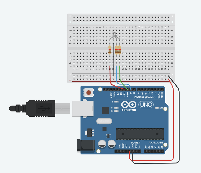
하드웨어 연결
회로도 및 연결
아두이노 우노로 RGB LED를 테스트하기 위해 아래와 같이 회로를 구성하였습니다. RGB Module의 R,G,B 단자는 PWM 출력이 가능한 11번, 10번, 9번 포트로 각각 연결하였습니다.
Arduino Uno와 RGB LED Module 연결 회로도 및 연결 예시
예제1 : RGB LED On/Off 제어
예제1은 RGB LED를 ON/OFF 방식으로 제어하는 예제입니다. RGB 3개의 핀(3 Bit)으로 8가지 색 표현이 가능합니다.
코드
아래의 예제 코드는 1000ms 간격으로 RED -> GREEN -> BLUE -> YELLOW -> CYAN 색을 순회하는 코드입니다.
1 2 3 4 5 6 7 8 9 10 11 12 13 14 15 16 17 18 19 20 21 22 23 24 25 26 27 28 29 30 31 32 33 34 35 36 37 # define RED 11 // RGB LED Module의 RED 핀 # define GREEN 10 // RGB LED Module의 GREEN 핀 # define BLUE 9 // RGB LED Module의 BLUE 핀 void setup (){ pinMode (RED, OUTPUT ); pinMode (GREEN, OUTPUT ); pinMode (BLUE, OUTPUT ); } void loop (){ // RED digitalWrite (RED, HIGH ); digitalWrite (GREEN, LOW ); digitalWrite (BLUE, LOW ); delay ( 1000 ); // GREEN digitalWrite (RED, LOW ); digitalWrite (GREEN, HIGH ); digitalWrite (BLUE, LOW ); delay ( 1000 ); // BLUE digitalWrite (RED, LOW ); digitalWrite (GREEN, LOW ); digitalWrite (BLUE, HIGH ); delay ( 1000 ); // YELLOW digitalWrite (RED, HIGH ); digitalWrite (GREEN, HIGH ); digitalWrite (BLUE, LOW ); delay ( 1000 ); // CYAN digitalWrite (RED, LOW ); digitalWrite (GREEN, HIGH ); digitalWrite (BLUE, HIGH ); delay ( 1000 ); } Colored by Color Scripter cs
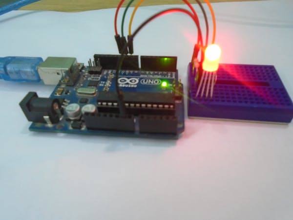
실행 결과
위 코드를 실행하면 1초 간격으로 LED 색상이 변하는 것을 확인 할 수 있습니다.
예제2 : RGB LED On/Off 제어
예제2는 RGB LED를 PWM으로 제어하는 예제입니다. RGB LED를 8 Bit PWM 출력으로 제어하는 경우 표현 가능한 색은 255(RED) x 255(GREEN) x 255(BLUE)으로 대략 16.8백만 가지의 컬러 표현이 가능합니다.
코드
아래의 코드는 analogWrite()함수를 사용하여 RGB LED를 제어하는 코드입니다. 1000ms 간격으로 빨->주->노->초->파->남->보 색을 RGB LED에 표시합니다.
Orange와 Yellow의 주석에 있는 RGB값은 쉽게 구글에서 구할 수 있는 색 좌표 값이고, 실제 코드에 적용한 RGB 값은 육안으로 실제로 Orange, Yellow 컬러가 비슷하게 나오는 값으로 튜닝한 값입니다.
1 2 3 4 5 6 7 8 9 10 11 12 13 14 15 16 17 18 19 20 21 22 23 24 25 26 27 28 29 30 31 32 33 34 35 36 37 38 39 40 41 42 43 44 45 46 47 # define RED 11 // RGB LED Module의 RED 핀 # define GREEN 10 // RGB LED Module의 GREEN 핀 # define BLUE 9 // RGB LED Module의 BLUE 핀 void setup (){ pinMode (RED, OUTPUT ); pinMode (GREEN, OUTPUT ); pinMode (BLUE, OUTPUT ); } void loop (){ // Red (255,0,0) analogWrite (RED, 255 ); analogWrite (GREEN, 0 ); analogWrite (BLUE, 0 ); delay ( 1000 ); // Orange (255,127,0) analogWrite (RED, 255 ); analogWrite (GREEN, 20 ); analogWrite (BLUE, 0 ); delay ( 1000 ); // Yellow (255,255,0) analogWrite (RED, 255 ); analogWrite (GREEN, 80 ); analogWrite (BLUE, 0 ); delay ( 1000 ); // Green (0,255,0) analogWrite (RED, 0 ); analogWrite (GREEN, 255 ); analogWrite (BLUE, 0 ); delay ( 1000 ); // Blue (0,0,255) analogWrite (RED, 0 ); analogWrite (GREEN, 0 ); analogWrite (BLUE, 255 ); delay ( 1000 ); // Indigo (0,5,70) analogWrite (RED, 0 ); analogWrite (GREEN, 5 ); analogWrite (BLUE, 70 ); delay ( 1000 ); // Purple (100,0,255) analogWrite (RED, 100 ); analogWrite (GREEN, 0 ); analogWrite (BLUE, 255 ); delay ( 1000 ); } Colored by Color Scripter cs
실행 결과
아래 영상은 위 코드의 실행 결과입니다. 구형 휴대폰으로 촬영하여 실제로 보는 것보다 색감이 잘 잡히지 않음을 고려해주세요.
마무리
이번 포스트에서는 RGB LED를 사용하는 기초적인 방법으로 LED를 ON/OFF하는 방식과 PWM을 사용하는 방식의 코드를 소개 하였습니다. 아두이노 아날로그 출력 PWM 사용에 대한 기초적인 내용은 하단의 관련 포스트를 참고해주세요.
끝까지 읽어 주셔서 감사합니다.😄
So you have finished reading the 아두 이노 rgb led topic article, if you find this article useful, please share it. Thank you very much. See more: 아두이노 rgb led 모듈, 아두이노 rgb led 여러개, rgb led바, led 아두이노, Arduino RGB LED, 아두이노 led 제어, RGB LED datasheet, 아두이노 3색 LED PWM