
You are looking for information, articles, knowledge about the topic nail salons open on sunday near me stm32 i2c hal on Google, you do not find the information you need! Here are the best content compiled and compiled by the https://chewathai27.com/to team, along with other related topics such as: stm32 i2c hal HAL_I2C_Master_Transmit, STM32 I2C example, I2C STM32, Hal i2c, I2C STM32F4, I2C STM32 Arduino, STM32 I2C LCD, I2C between two stm32
STM32F1: Giao tiếp I2C với STM32
- Article author: deviot.vn
- Reviews from users: 28785
 Ratings
 - Top rated: 4.3
- Lowest rated: 1
- Summary of article content: Articles about STM32F1: Giao tiếp I2C với STM32 SDA – Serial Data Line: Đường truyền nhận dữ liệu. Chip STM32F103 hỗ trợ cho chúng ta 2 bộ I2C, lần lượt là I2C1, I2C2 tương ứng với các chân:. …
- Most searched keywords: Whether you are looking for STM32F1: Giao tiếp I2C với STM32 SDA – Serial Data Line: Đường truyền nhận dữ liệu. Chip STM32F103 hỗ trợ cho chúng ta 2 bộ I2C, lần lượt là I2C1, I2C2 tương ứng với các chân:.
- Table of Contents:
STM32 I2C Tutorial HAL Code Examples Slave & Master – DMA / Interrupt
- Article author: deepbluembedded.com
- Reviews from users: 10568 Ratings
- Top rated: 4.5
- Lowest rated: 1
- Summary of article content: Articles about STM32 I2C Tutorial HAL Code Examples Slave & Master – DMA / Interrupt 2. I2C Hardware In STM32 … I2C (inter-integrated circuit) bus Interface serves as an interface between the microcontroller and the serial I2C bus. It proves … …
- Most searched keywords: Whether you are looking for STM32 I2C Tutorial HAL Code Examples Slave & Master – DMA / Interrupt 2. I2C Hardware In STM32 … I2C (inter-integrated circuit) bus Interface serves as an interface between the microcontroller and the serial I2C bus. It proves … STM32 I2C Tutorial With HAL Code Examples. STM32 i2c slave HAL code example. I2C DMA interrupt polling examples. I2C Scanner, TX, RX
- Table of Contents:
Categories
Search The Blog
Resources
Getting Started with STM32 – I2C Example
- Article author: www.digikey.be
- Reviews from users: 20853 Ratings
- Top rated: 4.4
- Lowest rated: 1
- Summary of article content: Articles about
Getting Started with STM32 – I2C Example
Let’s look at how to connect a simple I2C device to a STM32 Nucleo board to read temperature data using the STM32 HAL API. … - Most searched keywords: Whether you are looking for
Getting Started with STM32 – I2C Example
Let’s look at how to connect a simple I2C device to a STM32 Nucleo board to read temperature data using the STM32 HAL API. STM32, Nucleo, HAL API, digikey, makerLet’s look at how to connect a simple I2C device to a STM32 Nucleo board to read temperature data using the STM32 HAL API. - Table of Contents:
By ShawnHymel
Key Parts and Components
Project Details
Get Involved

STM32 I2C Master using HAL
- Article author: embeddedexplorer.com
- Reviews from users: 14624 Ratings
- Top rated: 3.9
- Lowest rated: 1
- Summary of article content: Articles about STM32 I2C Master using HAL STM32 I2C Master using HAL … I2C (Inter Integrated Cicuit) is a protocol commonly used in embedded systems to exchange data between devices involving a master … …
- Most searched keywords: Whether you are looking for STM32 I2C Master using HAL STM32 I2C Master using HAL … I2C (Inter Integrated Cicuit) is a protocol commonly used in embedded systems to exchange data between devices involving a master … Learn STM32 I2C module by building a project in STM32CubeIDE to read data from an I2C slave device and log received data to a console.
- Table of Contents:
Project description
Project Implementation
Wrapping Up
Related Posts
STM32
Embedded Explorer
Categories
About
ST Community
- Article author: community.st.com
- Reviews from users: 26974 Ratings
- Top rated: 3.7
- Lowest rated: 1
- Summary of article content: Articles about ST Community … an I2C slave device with interrupts using the STM32CubeMX and STM32Cube HAL … and control the master I2C communications with the STM32 I2C slave code. …
- Most searched keywords: Whether you are looking for ST Community … an I2C slave device with interrupts using the STM32CubeMX and STM32Cube HAL … and control the master I2C communications with the STM32 I2C slave code.
- Table of Contents:
STM32 I2C Configuration using Registers » ControllersTech
- Article author: controllerstech.com
- Reviews from users: 33125 Ratings
- Top rated: 3.5
- Lowest rated: 1
- Summary of article content: Articles about STM32 I2C Configuration using Registers » ControllersTech STM32 I2C Configuration using Registers · Enable the I2C and GPIO CLOCKS · Configure the Pins for I2C · Set the I2C clock · Enable the I2C · I2C START · I2C WRITE. …
- Most searched keywords: Whether you are looking for STM32 I2C Configuration using Registers » ControllersTech STM32 I2C Configuration using Registers · Enable the I2C and GPIO CLOCKS · Configure the Pins for I2C · Set the I2C clock · Enable the I2C · I2C START · I2C WRITE. This tutorial will cover both transmission and reception using the I2C in STM32 and the configuration will remain common in both the processes.
- Table of Contents:
mastering-stm32/stm32f4xx_hal_i2c.c at master · cnoviello/mastering-stm32 · GitHub
- Article author: github.com
- Reviews from users: 1412 Ratings
- Top rated: 4.7
- Lowest rated: 1
- Summary of article content: Articles about mastering-stm32/stm32f4xx_hal_i2c.c at master · cnoviello/mastering-stm32 · GitHub @brief I2C HAL module driver. * This file proves firmware functions to manage the following. * functionalities of the Inter Integrated Circuit (I2C) … …
- Most searched keywords: Whether you are looking for mastering-stm32/stm32f4xx_hal_i2c.c at master · cnoviello/mastering-stm32 · GitHub @brief I2C HAL module driver. * This file proves firmware functions to manage the following. * functionalities of the Inter Integrated Circuit (I2C) … Repository of all examples presented in the “Mastering STM32” book – mastering-stm32/stm32f4xx_hal_i2c.c at master · cnoviello/mastering-stm32
- Table of Contents:
mastering-stm32nucleo-f411REsystemsrcstm32f4xxstm32f4xx_hal_i2cc
Footer
Using the I2C Interface on the STM32 Devices – VisualGDB Tutorials
- Article author: visualgdb.com
- Reviews from users: 47418 Ratings
- Top rated: 4.4
- Lowest rated: 1
- Summary of article content: Articles about Using the I2C Interface on the STM32 Devices – VisualGDB Tutorials We will connect 2 STM32 boards using their I2C interface, will go over the I2C packet format, and will show how to use the STM32 HAL API to send … …
- Most searched keywords: Whether you are looking for Using the I2C Interface on the STM32 Devices – VisualGDB Tutorials We will connect 2 STM32 boards using their I2C interface, will go over the I2C packet format, and will show how to use the STM32 HAL API to send …
- Table of Contents:
See more articles in the same category here: Chewathai27.com/to/blog.
STM32 I2C Tutorial HAL Code Examples Slave & Master
In this tutorial, we’ll be discussing the I2C hardware in STM32 microcontrollers. Starting with an introduction to the Inter-Integrated Circuit (I2C) communication. And we’ll get a closer look at the STM32 I2C hardware module and its internal functionalities, modes of operation, options, and configurations. In conclusion, we’ll take a look at the possible interrupt signals that can be triggered by the I2C hardware. And the different modes to perform I2C transmit & receive operations like (polling – interrupt – DMA) both as an I2C master and as a slave device as well.
Finally, we’ll check the available I2C configuration inside of CubeMX and how to configure & operate the peripheral using the provided HAL APIs. And that’s it for this theoretical tutorial. Next, we’ll do a handful of LABs to practice using I2C in different projects for communication and modules interfacing with STM32 microcontrollers.
1. Introduction To I2C Communication
I2C (i-square-c) is an acronym for “Inter-Integrated-Circuit” which was originally created by Philips Semiconductors (now NXP) back in 1982. I2CTM is a registered trademark for its respective owner and maybe it was the reason they call it “Two Wire Interface (TWI)” in some microcontrollers like Atmel AVR. The I2C is a multi-master, multi-slave, synchronous, bidirectional, half-duplex serial communication bus. It’s widely used for attaching lower-speed peripheral ICs to processors and microcontrollers in short-distance, intra-board communication.
I2C Modes & Bus Speeds
Originally, the I2C-bus was limited to 100 kbit/s operations. Over time there have been several additions to the specification so that there are now five operating speed categories. Standard-mode, Fast-mode (Fm), Fast-mode Plus (Fm+), and High-speed mode (Hs-mode) devices are downward-compatible. This means any device may be operated at a lower bus speed. Ultra Fast-mode devices are not compatible with previous versions since the bus is unidirectional.
Bidirectional bus:
Standard-Mode (Sm) , with a bit rate up to 100 kbit/s
Fast-Mode (Fm) , with a bit rate up to 400 kbit/s
Fast-Mode Plus (Fm+) , with a bit rate up to 1 Mbit/s
High-speed Mode (Hs-mode), with a bit rate up to 3.4 Mbit/s.
Unidirectional bus:
Ultra Fast-Mode (UFm), with a bit rate up to 5 Mbit/s
Note: You have to refer to the specific device datasheet to check the typical details for the i2c hardware specifications that have actually been implemented on-chip.
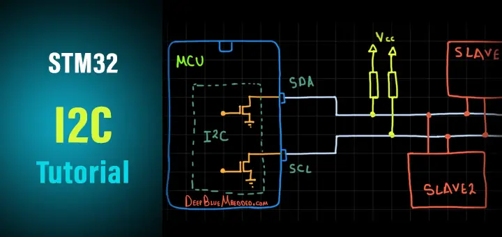
I2C Physical Layer (Hardware)
The I2C bus uses what’s known as an open-drain (open-collector) output driver for both SDA and SCL lines. Which as the name suggests is having each IO pin connected to the collector of the output driver transistor internally, while having it pulled up to Vcc with a resistor eternally. That’s why the default (IDLE) state for each line is HIGH when the open-drain driver is turned OFF. However, if we turn ON the output driver, the IO pin is driven LOW to the ground by the output driver transistor as you can see in the diagram below.
The I2C bus lines being “open-drain” bidirectional pins makes it perfect for multi-master multi-slave sort of communication without any risk of having collisions. And that’s due to having what’s called “Bus Arbitration” in case of multiple masters did initiate a transaction at the exact same time.
Anyone will write a 0 first while the other is writing a 1, will win the arbitration and continue its message and the other master will stop and wait till the end. That’s because of the nature of “Open-drain” output. To write a 0, we turn ON the output driver to pull the signal line to LOW. To write a 1, we turn OFF the output driver and the line will be pulled up to HIGH by the effect of the external resistors. That’s why bus arbitration is a very powerful feature for I2C communication.
SDA & SCL, Data Validity
Both SDA and SCL are bidirectional lines, connected to a positive supply voltage via a current-source or pull-up resistor. When the bus is free, both lines are HIGH. The output stages of devices connected to the bus must have an open-drain or open-collector to perform the wired-AND function.
Due to the variety of different technology devices (CMOS, NMOS, bipolar), that can be connected to the I2C-bus, the levels of the logical ‘0’ (LOW) and ‘1’ (HIGH) are not fixed and depend on the associated level of V DD . Input reference levels are set as 30 % and 70 % of V DD ; V IL is 0.3V DD and V IH is 0.7V DD . The data on the SDA line must be stable during the HIGH period of the clock. The HIGH or LOW state of the data line can only change when the clock signal on the SCL line is LOW. One clock pulse is generated for each data bit transferred.
Elements of I2C Transactions
A typical I2C message consists of some basic elements (conditions) that take place on the I2C bus sequentially and it always starts with a start condition (s). Followed by the desired slave device address (7-Bits or 10-Bits), then a R/W bit to determine whether the master (who initiated the S condition for communication) wants to read or write to this slave having that address. Then if the slave exists and works OK, it’ll acknowledge back to the master by sending an Acknowledge bit ACK otherwise, it’s considered a Negative Acknowledge NACK. Afterward, the byte of Data is sent, followed by an acknowledge from the slave. And finally, the master can terminate the communication by sending the Stop Condition (P) sequence.
We can summarize these conditions (elements) of I2C bus signaling as follows:
Start Condition (S)
Stop Condition (P)
Repeated Start (Restart) Condition (Sr)
Acknowledge ACK (A)
Not Acknowledge NACK (~A)
Address + R/W
Data Byte
Other topics and details of the I2C mechanics of its operation are discussed in detail in the article down below. Including I2C clock synchronization, stretching, I2C bus arbitration, addressing, I2C bus conditions, and more.
The linked I2C tutorial above is a full guide (+12k words!) that has all the information you may need to know if you’re just starting to learn about the topic. Take the time to check it out if you need to and come back to resume this tutorial and to see the I2C hardware peripheral implemented in STM32 microcontrollers and the extra features it does have. Then, we can proceed to build embedded software applications with an I2C interface to read sensors, external memories, etc.
2. I2C Hardware In STM32
2.1 STM32 I2C Hardware Overview
I2C (inter-integrated circuit) bus Interface serves as an interface between the microcontroller and the serial I2C bus. It provides multi-master capability and controls all I2C bus-specific sequencing, protocol, arbitration, and timing. It supports the standard mode (Sm, up to 100 kHz) and Fm mode (Fm, up to 400 kHz).
It may be used for a variety of purposes, including CRC generation and verification, SMBus (system management bus), and PMBus (power management bus). Depending on specific device implementation DMA capability can be available for reduced CPU overload.
2.2 STM32 I2C Main Features
Multimaster capability: the same interface can act as Master or Slave
I2C Master features: [ Clock generation – Start and Stop generation]
I2C Slave features: [Programmable I2C Address detection – Dual Addressing Capability to acknowledge 2 slave addresses – Stop bit detection]
Generation and detection of 7-bit/10-bit addressing and General Call
Supports different communication speeds:
– Standard Speed (up to 100 kHz)
– Fast Speed (up to 400 kHz)
Analog noise filter
2 Interrupt vectors:
– 1 Interrupt for successful address/ data communication
– 1 Interrupt for error condition
Optional clock stretching
1-byte buffer with DMA capability
Configurable PEC (packet error checking) generation or verification:
SMBus 2.0 Compatibility
PMBus Compatibility
3. STM32 I2C Hardware Functionalities
In this section, we’ll get a deep insight into the STM32 I2C module hardware, its block diagram, functionalities, modes of operations, and data reception/transmission.
3.1 STM32 I2C Block Diagram
As you can see in the I2C block diagram above, there is the main shift register, a buffer register, and some control logic units to handle all I2C transaction steps. Just like address match checking, generating the clock signal, filtering, error checking, and so on.
3.2 STM32 I2C Mode Selection
The interface can operate in one of the four following modes:
Slave transmitter
Slave receiver
Master transmitter
Master receiver
By default, it operates in slave mode. The interface automatically switches from slave to master, after it generates a START condition and from master to slave, if an arbitration loss or a Stop generation occurs, allowing multi-master capability. We’ll be creating a handful of example projects to operate the I2C peripheral in each one of all the 4 modes mentioned above.
3.3 STM32 I2C In Slave Mode
By default, the I2C interface operates in Slave mode. To switch from default Slave mode to Master mode a Start condition generation is needed. The peripheral input clock must be programmed in the I2C_CR2 register in order to generate correct timings. The peripheral input clock frequency must be at least:
2 MHz in Sm mode
4 MHz in Fm mode
As soon as a start condition is detected, the address is received from the SDA line and sent to the shift register. Then it is compared with the address of the interface. Following the address reception and after clearing ADDR, the slave receives bytes from the SDA line into the DR register via the internal shift register. After each byte, the interface generates an acknowledge pulse if the ACK bit is set.
If RxNE is set and the data in the DR register is not read before the end of the next data reception, the BTF bit is set and the interface waits until BTF is cleared by a read from I2C_SR1 followed by a read from the I2C_DR register, stretching SCL low. Clock stretching is essentially holding the clock line SCL LOW by the slave device which prevents any master device on the I2C bus from initiating any new transaction until that slave releases the SCL back again. That’s why you should be careful when using clock stretching in slave devices.
After the last data byte is transferred a Stop Condition is generated by the master. The interface detects this condition and sets the STOPF bit and generates an interrupt if the ITEVFEN bit is set. The STOPF bit is cleared by a read of the SR1 register followed by a write to the CR1 register.
3.4 STM32 I2C In Master Mode
In Master mode, the I2C interface initiates a data transfer and generates the clock signal. A serial data transfer always begins with a Start condition and ends with a Stop condition.
Master mode is selected as soon as the Start condition is generated on the bus with a START bit. The following is the required sequence in master mode.
Program the peripheral input clock in I2C_CR2 Register in order to generate correct timings
Configure the clock control registers
Configure the rise time register
Program the I2C_CR1 register to enable the peripheral
Set the START bit in the I2C_CR1 register to generate a Start condition
The peripheral input clock frequency must be at least:
2 MHz in Sm mode
4 MHz in Fm mode
3.5 STM32 I2C PEC (Packet Error Checking)
A PEC calculator has been implemented by STMicroelectronics in I2C hardware to improve the reliability of communication. The PEC is calculated by using the C(x) = x8 + x2 + x + 1 CRC-8 polynomial serially on each bit. By enabling PEC, you can have automatic error checking for large data packet transactions all done by hardware without adding any overhead on the software side.
However, you should also know that if the master device did lose the “arbitration” at any instance, this will corrupt the PEC. And the device will be set back to slave mode and waits until the arbitration “winner” master device finishes its message. Only then, you can start the process all over again.
4. STM32 I2C Error Conditions
There are some error conditions that could be detected by the I2C interface hardware to indicate some issues on the hardware level. The software can easily detect those error conditions by reading the corresponding flag bits for each error signal. The error conditions include:
Bus Error (BERR) – This error occurs when the I2C interface detects an external Stop or Start condition during an address or a data transfer.
Acknowledge Failure (AF) – This error occurs when the interface detects a non-acknowledge bit.
Arbitration Lost (ARLO) – This error occurs when the I2C interface detects an arbitration lost condition.
Overrun/Underrun Error (OVR) – An overrun error can occur in slave mode when clock stretching is disabled and the I2C interface is receiving data. The interface has received a byte and the data in DR has not been read before the next byte is received by the interface. Underrun error can occur in slave mode when clock stretching is disabled and the I2C interface is transmitting data. The interface has not updated the DR with the next byte before the clock comes for the next byte.
5. STM32 I2C Interrupts
The I2C interrupt events are connected to the same interrupt vector. So the I2C fires a single interrupt signal regardless of the source of it. The software will have to detect it. These events generate an interrupt if the corresponding Enable Control Bit is set.
6. STM32 I2C Master – Slave Modes TX & RX
In this section, I’ll list the possible ways that you can handle I2C transactions in your firmware applications. For code example LABs and testing, just click on the next tutorial button and keep going through this series of tutorials. There will be lots of examples and libraries that we’ll build based on I2C communication (e.g I2C_LCD, OLED, MPU6050 IMU, etc…).
I2C With Polling
The first and the easiest way to do anything in embedded software is just to poll for the hardware resource until it’s ready to move on to the next step in your program instructions. However, it’s the least efficient way to do things and the CPU will end up wasting so much time in a “busy-waiting” state.
It’s the same thing for both transmission and reception. You just wait until the current byte of data to be transmitted so you can start the next one and so on.
I2C With Interrupts
We can, however, enable the I2C interrupts and have a signal when it’s done and ready for servicing by CPU. Either for data that has been sent or received. Which saves a lot of time and has been always the best way to handle events like that.
However, in some “Time Critical” applications we need everything to be as deterministic, in time, as possible. And a major problem with interrupts is that we can’t expect when it’d arrive or during which task. That can potentially screw up the timing behavior of the system.
I2C With DMA
To operate at its maximum speed, the I2C needs to be fed with the data for transmission and the data received on the Rx buffer should be read to avoid overrun. To facilitate the transfers, the I2C features a DMA capability implementing a simple request/acknowledge protocol.
DMA requests are generated by Data Register becoming empty in transmission and Data Register becoming full in reception. Using the DMA will also free the CPU from doing the data transfers “peripheral <-> memory”. This will end up saving a lot of time and is considered to be the most efficient way to handle this peripheral to memory data transfer and vice versa.
7. STM32 I2C Device Memory Read / Write
In this section, I’ll explain a useful feature that has been implemented in HAL APIs for the I2C driver firmware library which is the device memory read/write. The following are the (Blocking) version for both of the 2 functions.
1 2 HAL_I2C_Mem_Write ( ) ; HAL_I2C_Mem_Read ( ) ;
There are other versions for other modes of operation like interrupt and interrupt+DMA. But let’s first explain what is the device memory read/write operation.
We, the developers, basically don’t need to do anything on the hardware level for the I2C interface to get it to work. The details of I2C operation mentioned earlier in this tutorial are mostly to give you an understanding of what’s happening at the hardware level. Despite the fact that most of those operations are done automatically by hardware when we set/clear some control bits.
Therefore, we only need to call some basic functions that represent a wrapper layer for the control registers set/clear bits sort of configuration. Just to get the I2C interface properly configured and also initiate data transmission/reception operations.
The basic functionality for transmitting data over I2C as a Master device is handled by the following HAL function.
1 HAL_I2C_Master_Transmit ( ) ;
It sends some data over I2C to a specific slave device address on the bus (if found) in a blocking mode. So, what’s the difference between the normal I2C_Transmit and I2C_Mem_Write? That’s what we’re trying to answer in this section. For that, let’s consider as an example the MPU6050 IMU device.
The IMU has an internal I2C device address so that any master on the bus can easily address this sensor module. Internally, the MPU6050 itself has some registers with a unique address for each of them. Generally speaking, we need to set some values for the internal registers of the IMU in order to configure it as per our application, and also read some registers in which the IMU data is located.
So, if you’ve got a master STM32 uC and would like to get the readings of the MPU6050 IMU, you’d need to do the following as stated in the datasheet.
As you can see, the Master (STM32 uC) has to start the transaction. Then send the AD+W (the address of the MPU6050 module itself) for writing operation. The master then writes out the internal register address (RA) inside the MPU6050 that we’d like to read. The slave will therefore acknowledge the command and send out the data located in that specific register. Finally, the master will terminate the communication.
This is how to read a register at a specific address inside a module that has its unique address as well on the I2C bus!
You can do all of that manually with the provided basic HAL APIs or use the Mem_Write / Mem_Read collection of functions that support all modes (blocking – interrupt – DMA). We’ll be putting all of those functions under testing in the upcoming tutorials and LABs to get more familiar with them.
8. SPI Configuration In CubeMX
In the next few tutorials, we’ll be doing some practical LABs to implement I2C Master/Slave (TX & RX) code examples. In which we’ll be using the CubeMX software tool to configure the I2C hardware. Therefore, in this section, I’ll introduce to you the features and options that can be configured within CubeMX GUI for I2C peripheral.
Here is the configuration tab for the I2C peripheral in CubeMX. And those are the possible modes for I2C.
Let’s pick the “I2C” mode. Now, you’ll find that we’re able to set the clock rate for master mode. And if you’re going to operate in slave mode, you can set the I2C device address length & value, and enable/disable the clock stretching feature that we’ve discussed earlier.
We can also enable/disable interrupts for I2C in the NVIC tab if you’re willing to use interrupt mode instead of polling the peripheral. And the same goes for the DMA, you can click the DMA tab to “Add” a DMA channel dedicated to I2C transfer and configure its parameters.
9. STM32 I2C HAL Functions APIs
1. STM32 I2C “Blocking” HAL Functions (Blocking Mode)
Master Transmission
1 HAL_I2C_Master_Transmit ( I2C_HandleTypeDef * hi2c , uint16_t DevAddress , uint8_t * pData , uint16_t Size , uint32_t Timeout ) ;
Master Reception
1 HAL_I2C_Master_Receive ( I2C_HandleTypeDef * hi2c , uint16_t DevAddress , uint8_t * pData , uint16_t Size , uint32_t Timeout ) ;
Slave Transmission
1 HAL_I2C_Slave_Transmit ( I2C_HandleTypeDef * hi2c , uint8_t * pData , uint16_t Size , uint32_t Timeout ) ;
Slave Reception
1 HAL_I2C_Slave_Receive ( I2C_HandleTypeDef * hi2c , uint8_t * pData , uint16_t Size , uint32_t Timeout ) ;
Device Memory Write
1 HAL_I2C_Mem_Write ( I2C_HandleTypeDef * hi2c , uint16_t DevAddress , uint16_t MemAddress , uint16_t MemAddSize , uint8_t * pData , uint16_t Size , uint32_t Timeout ) ;
Device Memory Read
1 HAL_I2C_Mem_Read ( I2C_HandleTypeDef * hi2c , uint16_t DevAddress , uint16_t MemAddress , uint16_t MemAddSize , uint8_t * pData , uint16_t Size , uint32_t Timeout ) ;
2. STM32 I2C Interrupt Mode HAL Functions (Non-Blocking Mode)
Master Transmission
1 HAL_I2C_Master_Transmit_IT ( I2C_HandleTypeDef * hi2c , uint16_t DevAddress , uint8_t * pData , uint16_t Size ) ;
After calling the above function, the I2C peripheral will start sending all the data bytes in the buffer one by one until it’s done. When it’s done this function below will be called and executed, if you’d like to do something upon data transmission completion, then add that to your code in the application source file (main.c).
1 2 3 4 void HAL_I2C_MasterTxCpltCallback ( I2C_HandleTypeDef * hi2c ) { // TX Done .. Do Something! }
Master Reception
1 HAL_I2C_Master_Receive_IT ( I2C_HandleTypeDef * hi2c , uint16_t DevAddress , uint8_t * pData , uint16_t Size ) ;
After calling the above function, the I2C peripheral will start receiving all the incoming data bytes in the buffer one by one until it’s done. When it’s done this function below will be called and executed, if you’d like to do something upon data reception completion, then add that to your code in the application source file (main.c).
1 2 3 4 void HAL_I2C_MasterRxCpltCallback ( I2C_HandleTypeDef * hi2c ) { // RX Done .. Do Something! }
Similar APIs are also available for slave mode of operation.
3. STM32 I2C DMA Mode HAL Functions (Non-Blocking Mode)
Master Transmission
1 HAL_I2C_Master_Transmit_DMA ( I2C_HandleTypeDef * hi2c , uint16_t DevAddress , uint8_t * pData , uint16_t Size ) ;
After calling the above function, the I2C peripheral will start sending all the data bytes in the buffer one by one until it’s done (in DMA Mode). When it’s done this function below will be called and executed, if you’d like to do something upon data transmission completion, then add that to your code in the application source file (main.c).
1 2 3 4 void HAL_I2C_MasterTxCpltCallback ( I2C_HandleTypeDef * hi2c ) { // TX Done .. Do Something! }
Master Reception
1 HAL_I2C_Master_Receive_DMA ( I2C_HandleTypeDef * hi2c , uint16_t DevAddress , uint8_t * pData , uint16_t Size ) ;
After calling the above function, the I2C peripheral will start receiving all the incoming data bytes in the buffer one by one until it’s done (in DMA Mode). When it’s done this function below will be called and executed, if you’d like to do something upon data reception completion, then add that to your code in the application source file (main.c).
1 2 3 4 void HAL_I2C_MasterRxCpltCallback ( I2C_HandleTypeDef * hi2c ) { // RX Done .. Do Something! }
Similar APIs are also available for slave mode of operation.
4. STM32 I2C Device Check
This is a useful utility to check if a slave device on the I2C is actually existing and working or not.
1 AL_I2C_IsDeviceReady ( I2C_HandleTypeDef * hi2c , uint16_t DevAddress , uint32_t Trials , uint32_t Timeout ) ;
The I2C Communication Bus Demonstrated in This Tutorial Will Be Used In The Following Next Tutorials:
MCU – MCU Communication Over I2C
External Serial I2C EEPROM
OLED Display
I2C LED Interface
and more…
That’s it for this tutorial. If you’d like to see the practical LAB examples for I2C and other interfacing projects and libraries we’ll build using this peripheral, just keep progressing through this series of tutorials and click to the next tutorial link down below.
Did you find this helpful? If yes, please consider supporting this work and sharing these tutorials!
Stay tuned for the upcoming tutorials and don’t forget to SHARE these tutorials. And consider SUPPORTING this work to keep publishing free content just like this!
Share this: Facebook
Telegram
More
Skype
Related
Bài 10: Giao thức I2C, lập trình STM32 với module RTC DS3231
Giao thức I2C là một chuẩn truyền thông đồng bộ trong vi xử lý. Giao thức này được sử dụng rất nhiều trong thiết kế vì tính đơn giản và dễ dàng làm việc. Tuy nhiên bù lại tốc độ thường không cao và chỉ sử dụng trong mạch (on board)
Bài 10 trong serie Học lập trình STM32 từ A tới Z
I2C viết tắt của Inter- Integrated Circuit là một phương thức giao tiếp được phát triển bởi hãng Philips Semiconductors. Dùng để truyền tín hiệu giữa vi xử lý và các IC trên các bus nối tiếp.
Đặc điểm:
Tốc độ không cao
Thường sử dụng onboard với đường truyền ngắn
Nối được nhiều thiết bị trên cùng một bus
Giao tiếp đồng bộ, sử dụng Clock từ master
Sử dụng 7 bit hoặc 10 bit địa chỉ
Chỉ sử dụng 2 chân tín hiệu SDA, SCL
Có 2 tốc độ tiêu chuẩn là Standard mode (100 kb/s)và Low mode (10 kbit/s)
Kết nối vật lý của giao thức I2C
Bus I2C sử dụng 2 dây tín hiệu là SDA (Serial Data Line) và SCL (Serial Clock Line). Dữ liệu truyền trên SDA được đồng bộ với mỗi xung SCL. Đường SCL chỉ master mới có quyền điều khiển.
Tất cả các thiết bị đều dùng chung 2 đường tín hiệu này.
Bài 10: Giao thức I2C, lập trình STM32 với module RTC DS3231 22
Hai đường bus SDA và SCL hoạt động ở chế độ Open Drain hay cực máng hở. Nghĩa là tất cả các thiết bị trong mạng đều chỉ có thể lái 2 chân này về 0 chứ ko thể kéo lên 1. Để tránh việc sảy ra ngắn mạch khi thiết bị này kéo lên cao, thiết bị kia kéo xuống thấp.
Để giữ mức logic là 1 ở trạng thái mặc định phải mắc thêm 2 điện trở treo lên Vcc (thường từ 1k – 4k7).
Mỗi Bus I2C sẽ có 3 chế độ chính:
Một Master, nhiều Slave
Nhiều master, nhiều Slave
Một Master, một Slave
Một master nhiều Slave
Nhiều Master, nhiều Slave
Tại một thời điểm truyền nhận dữ liệu chỉ có một Master được hoạt động, điều khiển dây SCL và phát tín hiệu bắt đầu tới các Slave.
Tất cả các thiết bị đáp ứng sự điều hướng của Master gọi là Slave. Giữa các Slave với nhau, phân biệt bằng 7bit địa chỉ.
Cách truyền dữ liệu của giao thức I2C
Giao thức (phương thức giao tiếp) là cách các thiết bị đã thống nhất với nhau khi sử dụng một chuẩn nào đó để truyền và nhận tín hiệu.
Dữ liệu được truyền đi trên dây SDA được thực hiện như sau:
Master thực hiện điều kiện bắt đầu I2C (Start Condition) Gửi địa chỉ 7 bit + 1bit Đọc/Ghi (R/W) để giao tiếp muốn đọc hoặc ghi dữ liệu tại Slave có địa chỉ trên Nhận phải hồi từ Bus, nếu có một bit ACK (Kéo SDA xuống thấp) Master sẽ gửi dữ liệu Nếu là đọc dữ liệu R/W bit = 1, chân SDA của master sẽ là input, đọc dữ liệu từ Slave gửi về. Nếu là ghi dữ liệu R/W = 0, chân SDA sẽ là output ghi dữ liệu vào Slave Truyền điều khiện kết thúc (Stop Condition)
Mỗi lần giao tiếp có cấu trúc như sau:
Bài 10: Giao thức I2C, lập trình STM32 với module RTC DS3231 23
Start condition( Điều khiện bắt đầu)
Bất cứ khi nào một thiết bị chủ / IC quyết định bắt đầu một giao dịch, nó sẽ chuyển mạch SDA từ mức điện áp cao xuống mức điện áp thấp trước khi đường SCL chuyển từ cao xuống thấp.
Khi điều kiện bắt đầu được gửi bởi thiết bị Master, tất cả các thiết bị Slave đều hoạt động ngay cả khi chúng ở chế độ ngủ (sleep mode) và đợi bit địa chỉ.
Bài 10: Giao thức I2C, lập trình STM32 với module RTC DS3231 24
Bit Read/Write
Bit này xác định hướng truyền dữ liệu. Nếu thiết bị Master / IC cần gửi dữ liệu đến thiết bị Slave, bit này được thiết lập là ‘0’. Nếu IC Master cần nhận dữ liệu từ thiết bị Slave, bit này được thiết lập là ‘1’.
Bit ACK / NACK
ACK / NACK là viết tắt của Acknowledged/Not-Acknowledged. Nếu địa chỉ vật lý của bất kỳ thiết bị Slave nào trùng với địa chỉ được thiết bị Master phát, giá trị của bit này được set là ‘0’ bởi thiết bị Slave. Ngược lại, nó vẫn ở mức logic ‘1’ (mặc định).
Khối dữ liệu
Nó bao gồm 8 bit và chúng được thiết lập bởi bên gửi, với các bit dữ liệu cần truyền tới bên nhận. Khối này được theo sau bởi một bit ACK / NACK và được set thành ‘0’ bởi bên nhận nếu nó nhận thành công dữ liệu. Ngược lại, nó vẫn ở mức logic ‘1’.
Sự kết hợp của khối dữ liệu theo sau bởi bit ACK / NACK được lặp lại cho đến quá trình truyền dữ liệu được hoàn tất.
Điều kiện kết thúc (Stop condition)
Sau khi các khung dữ liệu cần thiết được truyền qua đường SDA, thiết bị Master chuyển đường SDA từ mức điện áp thấp sang mức điện áp cao trước khi đường SCL chuyển từ cao xuống thấp.
Bài 10: Giao thức I2C, lập trình STM32 với module RTC DS3231 25
Giới thiệu chip thời gian thực DS3231
DS3231 là chip thời gian thực, giao tiếp thông qua giao thức I2C. Làm việc tại dải điện áp từ 2.3 đến 5.5V, tích hợp sẵn thạch anh nội nên rất nhỏ gọn.
Có 2 chế độ hẹn giờ có thể Config từng giây tới ngày trong tháng.
Datasheet các bạn down tại đây: https://datasheets.maximintegrated.com/en/ds/DS3231.pdf
DS3231 có địa chỉ 7bit là 0x68. Cách đọc và truyền được mô tả như trong hình
Bài 10: Giao thức I2C, lập trình STM32 với module RTC DS3231 26
Bảng sau mô ta địa chỉ lưu các giá trị ngày tháng năm đó là từ 0x00 tới 0x06.
Các byte từ 0x07 tới 0x0D lưu giá trị Hẹn giờ A1M và A2M
Các byte từ 0x0E tới 0x12 là các thanh ghi điều khiển DS3231
Bài 10: Giao thức I2C, lập trình STM32 với module RTC DS3231 27
Cấu hình giao thức I2C trên STM32 CubeMX
Mở phần mềm, chọn chip STM32F103C8 nhấn start project.
Trong Sys chọn Debug : Serial Wire. Nêu rõ trong Bài 3
Trong Tab Connectivity: Chọn giao thức I2C1
Mode: I2C
Parameter: để mặc định với Speed mode là standard, Clock speed 100khz.
Trong NVIC tick chọn bật ngắt cho I2C event.
Bài 10: Giao thức I2C, lập trình STM32 với module RTC DS3231 28
Config thêm PC13 là Led để kiểm tra trạng thái I2C
Bài 10: Giao thức I2C, lập trình STM32 với module RTC DS3231 29
Đặt tên project rồi Gencode
Bài 10: Giao thức I2C, lập trình STM32 với module RTC DS3231 30
Lập trình giao thức I2C
Trong KeilC chúng ta cấu hình như sau.
Khai báo địa chỉ của DS3231 là 0x68<<1. Các bạn phải dịch trái 1 đơn vị, vì các hàm i2c của hal yêu cầu vậy, bit thứ 8 là R/W sẽ được thêm vào ngay sau giá trị địa chỉ đó. Khai báo 2 nguyên mẫu hàm là BCD2DEC và DEC2BCD. Hai hàm này có tác dụng chuyển đổi dữ liệu kiểu BCD thành kiểu số thập phân(hay hexa, bin) và ngược lại. Vì dữ liệu đọc ghi vào Ds3231 là kiểu BCD Hai mảng lưu dữ liệu truyền và nhận từ BCD gồm 7 byte Một biến Status để đọc phản hồi của giao thức I2C Định nghĩa biến dữ liệu kiểu Struct để lưu các giá trị thời gian, sau đó khởi tạo 2 biến TimeNow để đọc giá trị thời gian và Time Set để cài đặt thời gian lên DS3231 Bài 10: Giao thức I2C, lập trình STM32 với module RTC DS3231 31 Sau đó viết hàm thực thi chuển đổi BCD2DEC và ngược lại Bài 10: Giao thức I2C, lập trình STM32 với module RTC DS3231 32 Các bạn tìm hàm Call back của giao thức I2C bằng cách tìm từ stm32f1xx_it.c như các bài trước, hoặc sử dụng list functions như sau. Mở tab Function ở phía work space project, mở file I2C và tìm tới hàm HAL_I2C_MemRxCpltCallback(I2C_HandleTypeDef *hi2c) Bài 10: Giao thức I2C, lập trình STM32 với module RTC DS3231 33 Copy phần thực thi của hàm đó và dán vào phần tiền xử lý trên main(). Sau đó thêm các bước sau. Điều hướng với lệnh if(hi2c->Instance == I2C1) nếu I2C1 sảy ra ngắt
Lưu các giá trị thời gian vào biến DS3231_TimeNow, với byte đầu tiên là giây, phút, giờ …. Sử dụng hàm chuyển đổi BCD2DEC
Bài 10: Giao thức I2C, lập trình STM32 với module RTC DS3231 34
Trong phần main(), đầu tiên chúng ta quét thử xem có thiết bị i2c nào kết nối không bằng cách.
Tắt Led PC13.
Cho hàm HAL_I2C_IsDeviceReady vào vòng lặp for, khi có kết nối, sẽ lưu địa chỉ của Slave đó vào Status và bật Led PC13
Bài 10: Giao thức I2C, lập trình STM32 với module RTC DS3231 35
Trước While(1) chúng ta sẽ ghi giá trị thời gian cho DS3231, hiện tại là 14h42 ngày 17 tháng 7 năm 2020. Ta sẽ ghi như sau. Sau đó ghi vào I2C bằng hàm HAL_I2C_Mem_Write_IT(&hi2c1,DS3231_ADDRESS,0x00,I2C_MEMADD_SIZE_8BIT,u8_tranBuffer,7);
Với 0x00 là địa chỉ bắt đầu,
I2C_MEMADD_SIZE_8BIT: kiểu dữ liệu bộ nhớ là 8bit
Gửi 7 byte: từ 0x00 –> 0x06
Bài 10: Giao thức I2C, lập trình STM32 với module RTC DS3231 36
Trong While(1) ta sẽ đọc dữ liệu từ DS3231 mỗi 5s một lần, ta làm như sau
Bài 10: Giao thức I2C, lập trình STM32 với module RTC DS3231 37
Nhấn Build F7 và nạp chương trình. Kết nối DS3231 SDA với PB7, SCL với PB6, sau đó nhấn vào debug .
Trong debug Add 2 biến Time_now và Status vào Watch 1
Bài 10: Giao thức I2C, lập trình STM32 với module RTC DS3231 38
Ta thấy rằng Status hiển thị 0xD1 nghĩa là 11010001 chính là địa chỉ 0x68 <<1 + R/W bit, với R/W = 1 nghĩa là đọc dữ liệu Thời gian sẽ hiển thị đúng với giá trị ta nạp vào và sẽ thay đổi mỗi 5S một lần. Bài 10: Giao thức I2C, lập trình STM32 với module RTC DS3231 39 Kết Giao thức I2C rất dễ sử dụng, vì các slave đều phản hồi lại master trước khi truyền, đó là các bit Ack Nack, vậy nên việc truyền sai địa chỉ, truyền sai dữ liệu rất dễ phát hiện. Hi vọng bạn đã nắm rõ cách thức hoạt động của giao thức I2C, hãy chuyển tới bài tiếp theo để tiếp tục học nhé
Getting Started with STM32 – I2C Example
Getting Started with STM32 – I2C Example
The STM32 line of microcontrollers are a popular implementation of the ARM Cortex-M core from STMicroelectronics. As with most microcontrollers, almost all STM32 parts come equipped with 1 (or more!) I2C interfaces.
If you have not set up STM32CubeIDE with your Nucleo board, you will need to do so following the steps outlined in this tutorial.
If video is your preferred medium, check out this video for how to use I2C with STM32:
Required Components
You will need the following components to complete this tutorial: https://www.digikey.com/short/p59jrr
Note that any Nucleo board may be used, but steps are shown for the Nucleo-L476RG.
TMP102 and I2C
The TMP102 is an extremely simple digital temperature sensor from Texas Instruments. It relies on I2C to communicate data to and from a host device. I recommend the SparkFun TMP102 Breakout Board to test the device.
Inter-Integrated Circuit (I2C) is a communication bus protocol developed by Philips Semiconductor (now NXP Semiconductors) in 1982. It is a relatively slow protocol but has seen widespread use due to its simplicity and robustness. Most microcontrollers have at least 1 I2C peripheral controller built in to the silicon.
If you would like to learn more about the I2C protocol, I recommend this tutorial from SparkFun.
By looking at the TMP102 datasheet, we can determine that retrieving temperature data from the temperature register would require a set of I2C write/read commands as follows:
Note that we need to first send out a write command from the STM32 to the TMP102 with 1 byte that contains the address of the temperature register in the TMP102 (address 0x00). We immediately follow that with a read command where we read 2 bytes from the TMP102. These 2 bytes will contain the temperature data.
Hardware Hookup
Connect your Nucleo to the TMP102 as shown in the following Fritzing diagram:
Create a New Project in STM32CubeIDE
Open STM32CubeIDE and click File > New > STM32 Project. Select the Nucleo-L476RG (or your preferred board) and name your project. Stick with the C target language. In the Pinout & Configuration window, assign PB8 and PB9 to I2C1_SCL and I2C1_SDA functions, respectively.
The pins should be colored yellow, which indicates that while the pins are assigned to a peripheral, that peripheral has not yet been initialized in the CubeMX software. On the left pane in CubeMX, select Categories > Connectivity > I2C1. In the Mode pane, change I2C Disable to I2C.
You should see the PB8 and PB9 pins turn green, indicating that we’ve fully configured the I2C peripheral.
Click File > Save and click Yes to generate code.
The Code
Open up main.c, and modify it to look like the following:
Copy Code /* USER CODE BEGIN Header */
/**
******************************************************************************
* @file : main.c
* @brief : Main program body
******************************************************************************
* @attention
*
*
© Copyright (c) 2019 STMicroelectronics. * All rights reserved.
*
* This software component is licensed by ST under BSD 3-Clause license,
* the “License”; You may not use this file except in compliance with the
* License. You may obtain a copy of the License at:
* opensource.org/licenses/BSD-3-Clause
*
******************************************************************************
*/
/* USER CODE END Header */
/* Includes ——————————————————————*/
#include “main.h”
/* Private includes ———————————————————-*/
/* USER CODE BEGIN Includes */
#include
#include
/* USER CODE END Includes */
/* Private typedef ———————————————————–*/
/* USER CODE BEGIN PTD */
/* USER CODE END PTD */
/* Private define ————————————————————*/
/* USER CODE BEGIN PD */
/* USER CODE END PD */
/* Private macro ————————————————————-*/
/* USER CODE BEGIN PM */
/* USER CODE END PM */
/* Private variables ———————————————————*/
I2C_HandleTypeDef hi2c1;
UART_HandleTypeDef huart2;
/* USER CODE BEGIN PV */
static const uint8_t TMP102_ADDR = 0x48 << 1; // Use 8-bit address static const uint8_t REG_TEMP = 0x00; /* USER CODE END PV */ /* Private function prototypes -----------------------------------------------*/ void SystemClock_Config(void); static void MX_GPIO_Init(void); static void MX_USART2_UART_Init(void); static void MX_I2C1_Init(void); /* USER CODE BEGIN PFP */ /* USER CODE END PFP */ /* Private user code ---------------------------------------------------------*/ /* USER CODE BEGIN 0 */ /* USER CODE END 0 */ /** * @brief The application entry point. * @retval int */ int main(void) { /* USER CODE BEGIN 1 */ HAL_StatusTypeDef ret; uint8_t buf[12]; int16_t val; float temp_c; /* USER CODE END 1 */ /* MCU Configuration--------------------------------------------------------*/ /* Reset of all peripherals, Initializes the Flash interface and the Systick. */ HAL_Init(); /* USER CODE BEGIN Init */ /* USER CODE END Init */ /* Configure the system clock */ SystemClock_Config(); /* USER CODE BEGIN SysInit */ /* USER CODE END SysInit */ /* Initialize all configured peripherals */ MX_GPIO_Init(); MX_USART2_UART_Init(); MX_I2C1_Init(); /* USER CODE BEGIN 2 */ /* USER CODE END 2 */ /* Infinite loop */ /* USER CODE BEGIN WHILE */ while (1) { // Tell TMP102 that we want to read from the temperature register buf[0] = REG_TEMP; ret = HAL_I2C_Master_Transmit(&hi2c1, TMP102_ADDR, buf, 1, HAL_MAX_DELAY); if ( ret != HAL_OK ) { strcpy((char*)buf, "Error Tx\r "); } else { // Read 2 bytes from the temperature register ret = HAL_I2C_Master_Receive(&hi2c1, TMP102_ADDR, buf, 2, HAL_MAX_DELAY); if ( ret != HAL_OK ) { strcpy((char*)buf, "Error Rx\r "); } else { //Combine the bytes val = ((int16_t)buf[0] << 4) | (buf[1] >> 4);
// Convert to 2’s complement, since temperature can be negative
if ( val > 0x7FF ) {
val |= 0xF000;
}
// Convert to float temperature value (Celsius)
temp_c = val * 0.0625;
// Convert temperature to decimal format
temp_c *= 100;
sprintf((char*)buf,
“%u.%u C\r
“,
((unsigned int)temp_c / 100),
((unsigned int)temp_c % 100));
}
}
// Send out buffer (temperature or error message)
HAL_UART_Transmit(&huart2, buf, strlen((char*)buf), HAL_MAX_DELAY);
// Wait
HAL_Delay(500);
/* USER CODE END WHILE */
/* USER CODE BEGIN 3 */
}
/* USER CODE END 3 */
}
// Rest of auto-generated Cube functions
// …
Let’s take a look at the I2C portion of the code. To begin reading temperature, we first send a write request to the TMP102 with the following HAL API function:
Copy Code ret = HAL_I2C_Master_Transmit(&hi2c1, TMP102_ADDR, buf, 1, HAL_MAX_DELAY);
We pass in a handle to our I2C typedef with &hi2c1 and the address of the TMP102 on the bus. Note that the address should be 0x48 (with A0 tied to ground on the TMP102), but we need to left-shift that byte by 1 bit, as we are using a 7-bit address. We also pass in our buffer, which is simply a uint8_t array, along with the number of bytes we wish to send (1 byte). Because this is a blocking function, we need to tell it how long to wait before giving up. We will use HAL_MAX_DELAY, which comes out to be something like 50 days. Feel free to use your own timeout period here.
The return value, which we store in ret, is a common HAL Status type. If the returned value is not equal to HAL_OK, we transmit an error message to the console. Otherwise, we continue to the read function:
Copy Code ret = HAL_I2C_Master_Receive(&hi2c1, TMP102_ADDR, buf, 2, HAL_MAX_DELAY);
This works similarly to the transmit function. We provide the I2C peripheral handle and the address of the TMP102 on the bus. While we pass in the same buffer, it will be used as an output. When the function returns, if all goes well, the bytes read from the TMP102 will be stored in that buffer. Since we expect 2 bytes from the TMP102 (temperature data is sent as 12 bits), we tell the function that we want to read 2 bytes. Finally, we use the HAL_MAX_DELAY to essentially have no timeout.
Again, we hope to have HAL_OK as our return value. If so, we can expect the buffer, buf, to contain our temperature data. We can then perform some math to transform the 12-bit value into a human readable format, like Celsius. The math for calculating the temperature data can be found in the Digital Temperature Output section of the TMP102 datasheet.
Running and Debugging
Save your code. Click Project > Build Project. The project should compile without any errors. When it’s done, click Run > Debug As > STM32 MCU C/C Application.
Click OK on the pop-up window asking you to set the debug configurations. The default configurations will work for now. Click Switch when asked about switching to a new perspective. Click the Resume button at the top of the toolbar to begin running code on the Nucleo board.
The installation process for STM32CubeIDE should have installed any necessary serial drivers for the Nucelo boards by default. If not, follow the instructions on this mbed page to install the drivers.
Open up your favorite serial terminal program and connect it to the COM port of your Nucleo board with a baud rate of 115200 (8 data bits, no parity, 1 stop bit). You should see temperature data (in Celsius) being reported twice per second.
Try lightly placing your finger on the TMP102 or breathing on it. You should see the reported temperature go up. If you remove the connections to SCL or SDA, you should see error messages being reported.
Resources and Going Further
Try talking to other I2C devices! Additionally, if you take a look at the I2C transmit and receive functions, you will see that they are blocking, which means that the program will not continue until those functions have completed. Take a look at the HAL API documentation for your particular board, and you’ll notice that there are lots of other I2C functions. The functions that end with _IT() rely on hardware interrupts within the STM32, which means you can construct non-blocking versions of our I2C communication. Give it a shot!
Overview of DigiKey’s STM32 offerings: https://www.digikey.com/en/product-highlight/s/stmicroelectronics/stm32-overview
DigiKey’s Nucleo offerings: https://www.digikey.com/en/product-highlight/s/stmicroelectronics/nucleo-development-boards
STM32 HAL API for L4/L4 : https://www.st.com/resource/en/user_manual/dm00173145.pdf
Download STM32CubeIDE: https://www.st.com/en/development-tools/stm32cubeide.html
So you have finished reading the stm32 i2c hal topic article, if you find this article useful, please share it. Thank you very much. See more: HAL_I2C_Master_Transmit, STM32 I2C example, I2C STM32, Hal i2c, I2C STM32F4, I2C STM32 Arduino, STM32 I2C LCD, I2C between two stm32